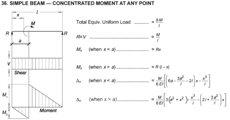
I was looking at the AISC simple beam tables and one scenario got me thinking.
Where does this given scenario actually occur? I understand these tables give us and approximation, but I'm not sure how to make this comparison against an modeled beam.
Note: At the location of maximum moment, the beam experiences a total magnitude of the applied moment. However, in terms of negative/positive moments, they are equally shared if the moment is placed at he center of the beam. [highlight yellow]Does this mean the beam design check considers both positives/negative moment at some infinitesimal distance away from each other?[/highlight]
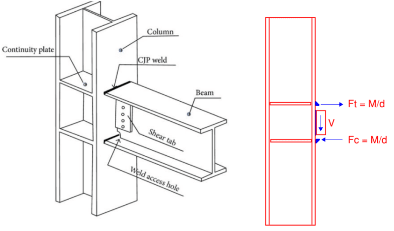
Take steel for example, typically our applied moment would be induced by some other discrete member that has torque on it. The mechanism by which this moment would "make it's way" into the simple span beam, would be a force couple with an accompanying shear load. Wouldn't the moment arm between the force couple prevent M1 and M2 from occurring at the same location.
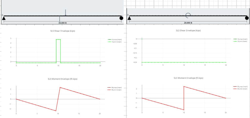
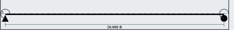
Take this model as an example:
Here is a 10ft tall W10X12, pinned top and bottom, with a 3ft long HSS3.5x0.3 cantilever. The live load on the end of the cantilever is 2K.
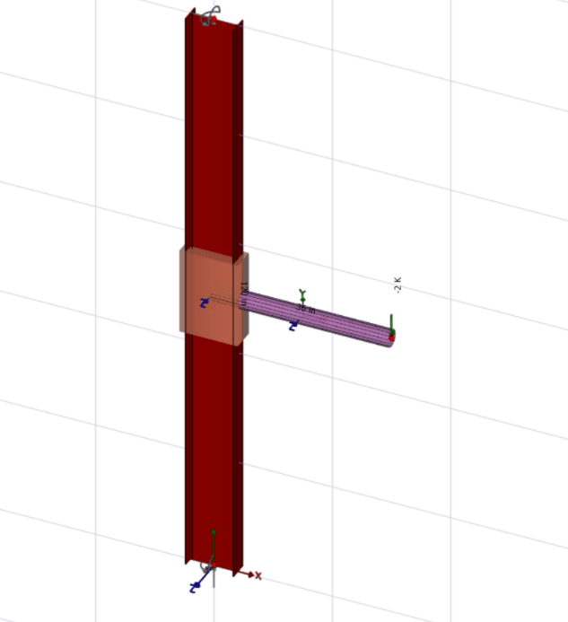
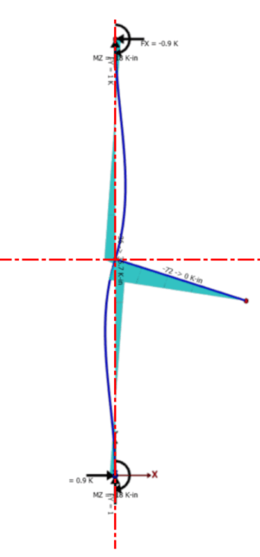
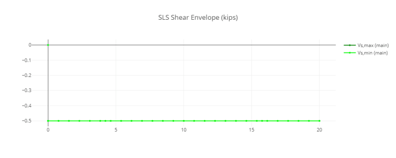
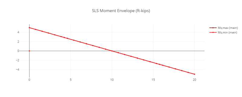
Graphing a diagram of the moment shows two points of maximum moment, with an offset between the two:
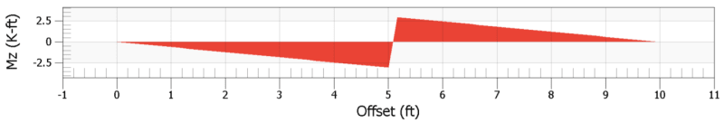
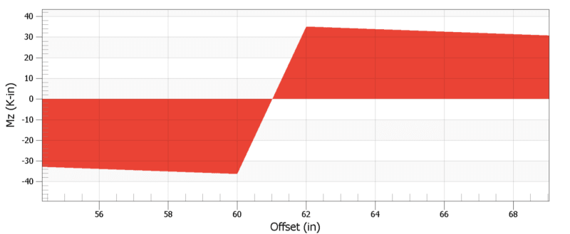
Zoomed in view of the moment in kips & inches. Interesting how the point of zero moment doesn't hover the 60in mark, as that's the true center of the load. Also, I would have expected the offset to occur over a length of at least 3 inches. Either way, this somewhat confirms my understanding that the load applied to this beam-column is actually two transverse loads with a moment arm between them.
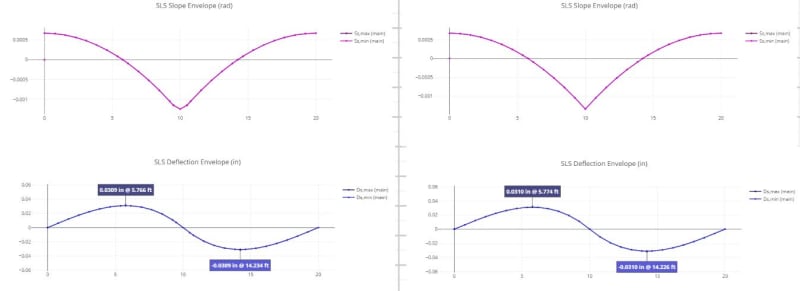
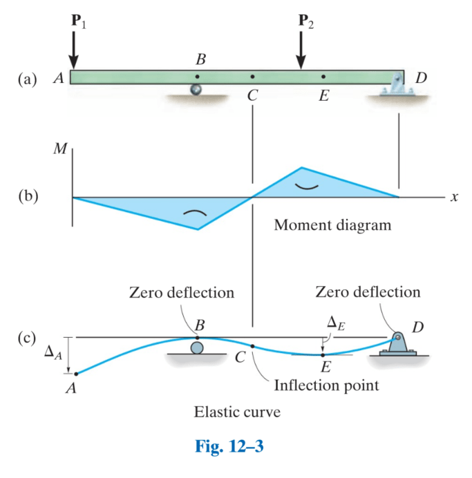
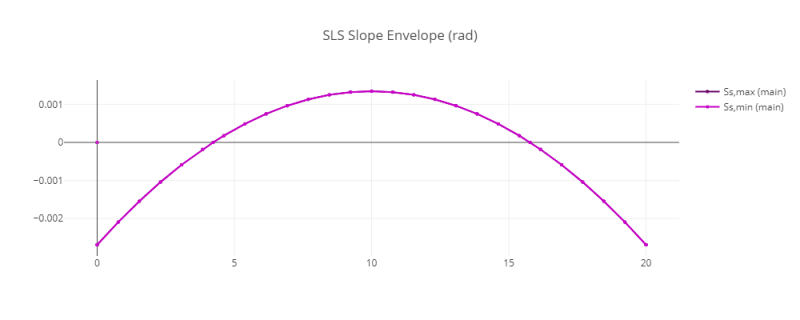
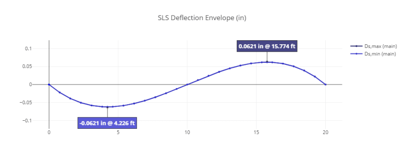
Another interesting thing is the relationship between the deflected shape and the location of maximum moments.
Beams loaded with this concentrated moment would take a deflected shape as shown below. According to the AISC table, the location of maximum moment is at the applied load, while in theory this is the location of inflection along the beam column.
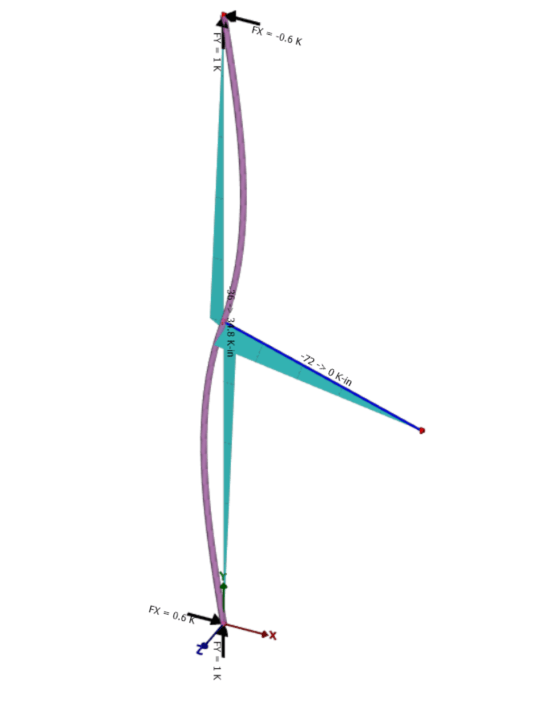
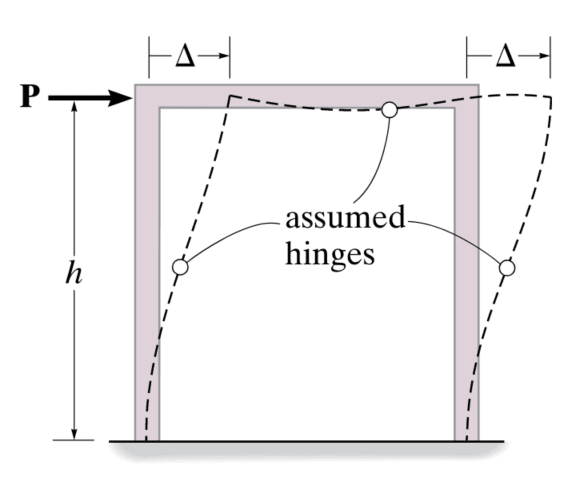
This is confirmed by a portal frame analysis. The beam columns for a fixed portal frame experiences S-type deflection and the inflection point of the member is assumed to have zero moment.
Where does this given scenario actually occur? I understand these tables give us and approximation, but I'm not sure how to make this comparison against an modeled beam.
Note: At the location of maximum moment, the beam experiences a total magnitude of the applied moment. However, in terms of negative/positive moments, they are equally shared if the moment is placed at he center of the beam. [highlight yellow]Does this mean the beam design check considers both positives/negative moment at some infinitesimal distance away from each other?[/highlight]
Take steel for example, typically our applied moment would be induced by some other discrete member that has torque on it. The mechanism by which this moment would "make it's way" into the simple span beam, would be a force couple with an accompanying shear load. Wouldn't the moment arm between the force couple prevent M1 and M2 from occurring at the same location.
Take this model as an example:
Here is a 10ft tall W10X12, pinned top and bottom, with a 3ft long HSS3.5x0.3 cantilever. The live load on the end of the cantilever is 2K.
Graphing a diagram of the moment shows two points of maximum moment, with an offset between the two:
Zoomed in view of the moment in kips & inches. Interesting how the point of zero moment doesn't hover the 60in mark, as that's the true center of the load. Also, I would have expected the offset to occur over a length of at least 3 inches. Either way, this somewhat confirms my understanding that the load applied to this beam-column is actually two transverse loads with a moment arm between them.
Another interesting thing is the relationship between the deflected shape and the location of maximum moments.
Beams loaded with this concentrated moment would take a deflected shape as shown below. According to the AISC table, the location of maximum moment is at the applied load, while in theory this is the location of inflection along the beam column.
This is confirmed by a portal frame analysis. The beam columns for a fixed portal frame experiences S-type deflection and the inflection point of the member is assumed to have zero moment.