Continue to Site

Eng-Tips is the largest engineering community on the Internet

Intelligent Work Forums for Engineering Professionals

  • Congratulations KootK on being selected by the Eng-Tips community for having the most helpful posts in the forums last week. Way to Go!

A simple beam scenario causing confusion 1

Status
Not open for further replies.

StrEng007

Structural
Aug 22, 2014
510
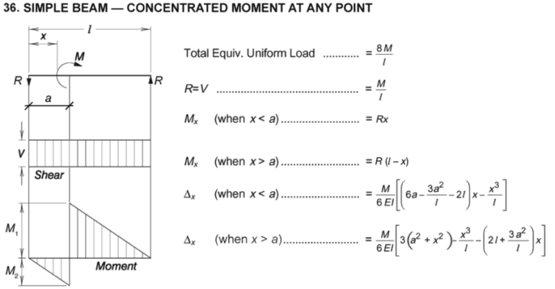
I was looking at the AISC simple beam tables and one scenario got me thinking.

Where does this given scenario actually occur? I understand these tables give us and approximation, but I'm not sure how to make this comparison against an modeled beam.
Screenshot_2023-12-12_112446_djb3kw.png


Note: At the location of maximum moment, the beam experiences a total magnitude of the applied moment. However, in terms of negative/positive moments, they are equally shared if the moment is placed at he center of the beam. [highlight yellow]Does this mean the beam design check considers both positives/negative moment at some infinitesimal distance away from each other?[/highlight]

Take steel for example, typically our applied moment would be induced by some other discrete member that has torque on it. The mechanism by which this moment would "make it's way" into the simple span beam, would be a force couple with an accompanying shear load. Wouldn't the moment arm between the force couple prevent M1 and M2 from occurring at the same location.

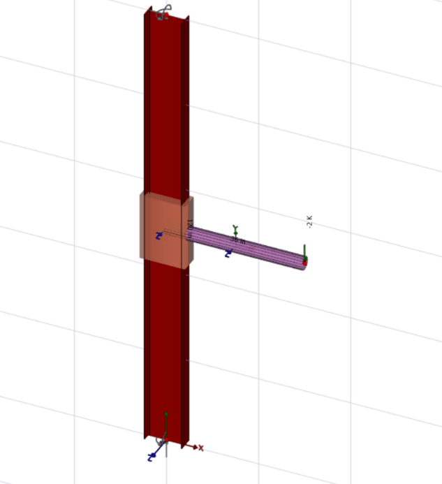
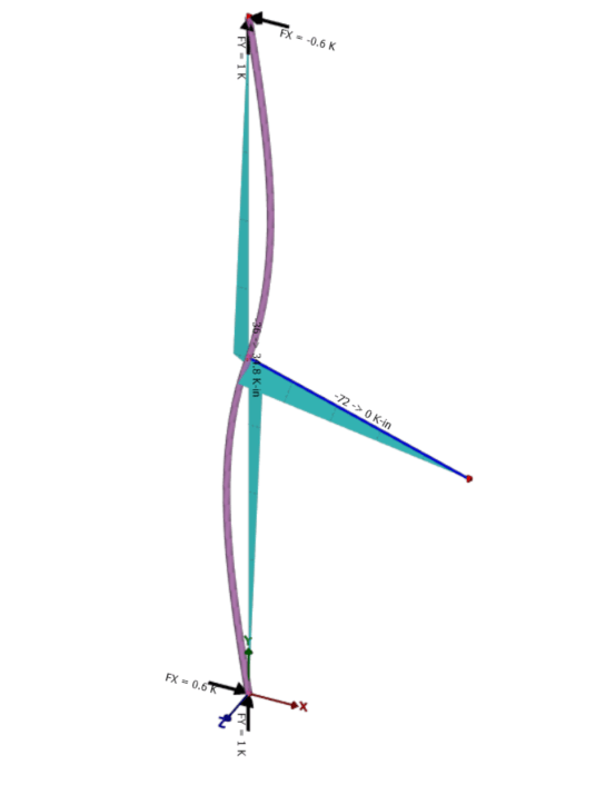
Take this model as an example:
Here is a 10ft tall W10X12, pinned top and bottom, with a 3ft long HSS3.5x0.3 cantilever. The live load on the end of the cantilever is 2K.
Screenshot_2023-12-12_112447_bmvt59.png


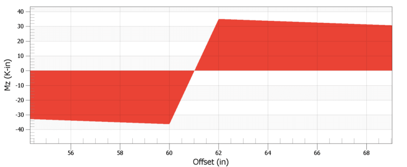
Graphing a diagram of the moment shows two points of maximum moment, with an offset between the two:
Screenshot_2023-12-12_112448_pwinrh.png


Zoomed in view of the moment in kips & inches. Interesting how the point of zero moment doesn't hover the 60in mark, as that's the true center of the load. Also, I would have expected the offset to occur over a length of at least 3 inches. Either way, this somewhat confirms my understanding that the load applied to this beam-column is actually two transverse loads with a moment arm between them.
Screenshot_2023-12-12_112449_k85goq.png


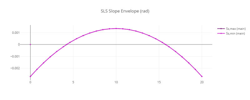
Another interesting thing is the relationship between the deflected shape and the location of maximum moments.
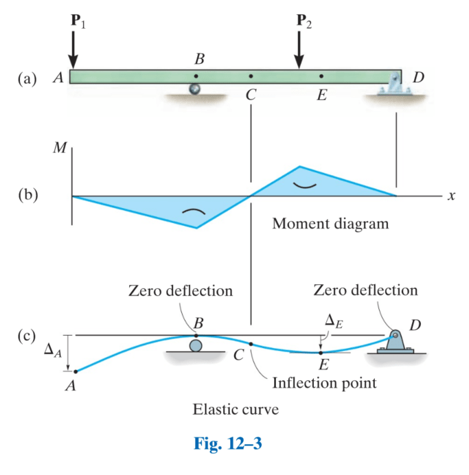
Beams loaded with this concentrated moment would take a deflected shape as shown below. According to the AISC table, the location of maximum moment is at the applied load, while in theory this is the location of inflection along the beam column.
Screenshot_2023-12-12_112_slpjqe.png


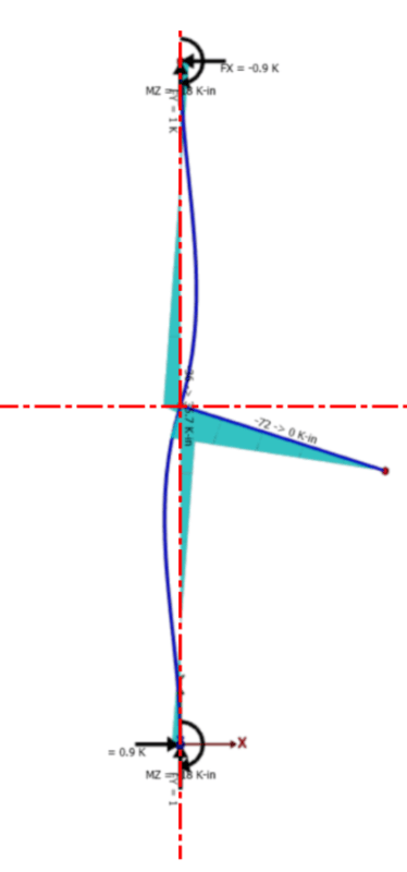
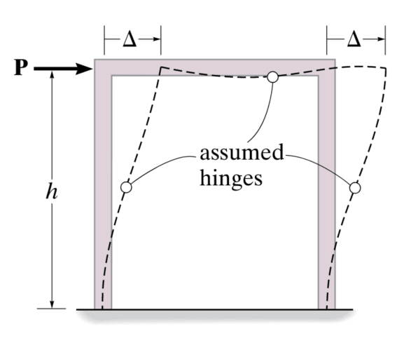
This is confirmed by a portal frame analysis. The beam columns for a fixed portal frame experiences S-type deflection and the inflection point of the member is assumed to have zero moment.
 
Replies continue below

Recommended for you

1. I think your graphs are set in your software to linearly draw moment lines from discreet points. If you have the ability to increase the number of discreet points along the member I think your graph would approach that of the AISC diagram.

2. While the point of inflection is at the point of moment application, note that the CURVATURE of the member is maximum at that point as well. Thus the maximum moment occurs at that midpoint.

 
Also the tables are not giving an approximation, it's the theoretical solution.

If you considered a free body of your column with the beam forces as loads, then you may well end up with something as shown for the moment. But the result you're seeing is probably due to what JAE has noted as typically analysis software will be using discrete line elements connected on centerlines to represent the members. Take a look at the shear and I'd imagine you won't see the panel shear effect on the shear diagram.

 
yeah, this happens a lot with simple beam plotting programs ... they're not designed for point loads, so what we draw as an instantaneous step change (in shear or BM) when we're drawing a beam loading diagram, but software uses points near the step change.

"Hoffen wir mal, dass alles gut geht !"
General Paulus, Nov 1942, outside Stalingrad after the launch of Operation Uranus.
 
When you take the applied moment as being applied at a point, that is an approximation to reality.
When you take the applied moment as two equal/opposite forces, that is just a different approximation to reality.
Similarly, any "point" load on a beam will have some non-zero dimension associated with it. Or else, you have an infinite contact stress at the point.
Any rigid connection will have some flexibility built in, any pinned connection will have some rigidity in reality.
One of the basic assumptions in deriving the deflection equations for beams is that you are not near a support, so you automatically have areas of the beam where that assumption is not valid.
 
StrEng007 said:
This is confirmed by a portal frame analysis. The beam columns for a fixed portal frame experiences S-type deflection and the inflection point of the member is assumed to have zero moment.

See attached (pg. 2). Are you talking about a portal frame with fixed bases and an applied lateral load? Then yes, your points of inflection = 0 moment in that case.

If you're talking about a portal frame with pinned bases and two floors under gravity load (the upper frame on pg 2 of my attachment), then I would say your inflection point at the first floor would be the location of the max moment in the columns, not 0 moment. Granted, it's a moment reversal from + to -, but I don't know that I would call that 0 moment.
 
StrEng007 said:
Does this mean the beam design check considers both positives/negative moment at some infinitesimal distance away from each other?
Yes the member must be designed for both positive and negative moments.

StrEng007 said:
...I understand these tables give us and approximation, ....
No, the ASIC beam tables give the exact solutions assuming Euler–Bernoulli beam behavior (no shear deformations)

StrEng007 said:
Graphing a diagram of the moment shows two points of maximum moment, with an offset between the two:
This is a result of how the analysis program functions, most just generate a number of sampling points along the beam to generate the diagrams as a results you get these artifacts at concentrated loadings.

StrEng007 said:
Either way, this somewhat confirms my understanding that the load applied to this beam-column is actually two transverse loads with a moment arm between them.
No, the beams are modeled node to node. The common node is rigidly connected to the surrounding members so they all have consistent deformations. Review this free textbook on the direct stiffness method: Matrix Structural Analysis, 2nd Edition

StrEng007 said:
The beam columns for a fixed portal frame experiences S-type deflection and the inflection point of the member is assumed to have zero moment.
In the pure analytical case no the inflection point does not have zero moment it is the location of change of sign of the moment. In reality the moment is likely the result of some form of force couple so there would be a 0 moment location.

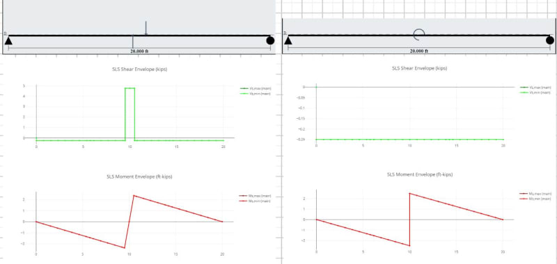
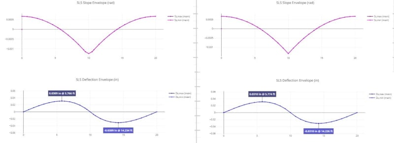
Close Point Load Couple vs True Concentrated Moment:
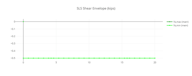
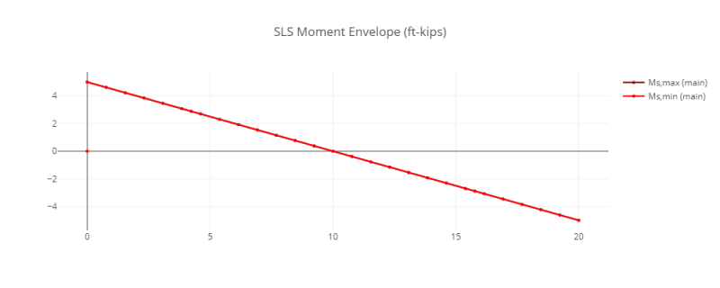
(notice the large shear delta in the coupled point load case)
Capture_jz7h8c.jpg

Capture2_oit4ch.jpg
 
JAE said:
1. I think your graphs are set in your software to linearly draw moment lines from discreet points. If you have the ability to increase the number of discreet points along the member I think your graph would approach that of the AISC diagram.

I see what you're saying. I cannot get the model to display the moment exactly like AISC, but I was able to increase the number of points along the line and see it's headed that way.

JAE said:
2. While the point of inflection is at the point of moment application, note that the CURVATURE of the member is maximum at that point as well. Thus the maximum moment occurs at that midpoint.

My apologies, I don't really see what you're saying. Is there another way you can explain it? From my point of view, the curvature is largest at approximately 1ft above and below the application of the moment.

Here is the deflected shape with a straight line run through the centerline of the column.
Screenshot_2023-12-12_141647_fcj4v0.png


Celt83 said:
No, the inflection point is not assumed to have zero moment.
I see what you mean from your images and I agree that the point of moment application is the location of maximum moment and the point of inflection.
I've done both free body diagrams by hand and got the same results as you've shown, I'm not debating that.

I was just comparing it to this scenarios from lateral loads on a portal frame which have zero moment at the location of inflection.

I had it ingrained that points of inflection equal zero moment.

Screenshot_2023-12-12_143407_ga7psx.png


Another scenario:
Screenshot_2023-12-12_144258_g3bejy.png


My original question was about where this scenario actually occurs. Isn't part of the reason we have continuity plates to ensure that moment enters the beam without local buckling failure. Through the continuity plates, we establish the idealized single point load moment as others have mentioned.
Screenshot_2023-12-12_142615_sdmrko.png
 
In terms of where it would actually occur, I think your quick 3D model is a good representation. Something like a bracket coming off a column to support a facade element or structural beam.
 
For your second example points B and E are technically also inflection points of the deflection curve but moment is not 0 at those locations.

A portal frame analysis works on the assumption that the column has no loading along it's length and moments at each end generating double curvature and 0 moment at column mid-height:

portal_vf90yo.jpg

portal_shear_o1y40t.png

portal_moment_aifga7.png

portal_slope_lkpom1.png

portal_delta_k1w1i5.png
 
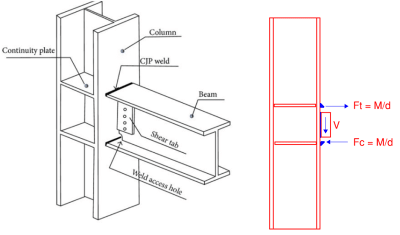
those continuity webs are there so the couple (Ft, Fc) forces are not applied directly to the flange of the supporting beam (as out-of-plane loads) but are instead sheared into the web of the supporting beam.

"Hoffen wir mal, dass alles gut geht !"
General Paulus, Nov 1942, outside Stalingrad after the launch of Operation Uranus.
 
milkshakelake said:
In terms of where it would actually occur, I think your quick 3D model is a good representation. Something like a bracket coming off a column to support a facade element or structural beam.
Gotcha. I wasn't talking about the type of structural setup that would lead to that sort of reaction. I was more hung up on the fact that AISC represents as a single point load, while I was wanting to rationalize that the more appropriate loading scenario would involve a force couple. In my mind, I imagine something extreme like a W36 beam that has a decent moment arm between the couple. As others have stated, our overall approach of applying loads is an approximation. I still see there being some sort of force couple, creating some sort of localized shear delta that Celt83 pointed out.

Speaking of... Celt, thank you for showing me your ways.

rb1957 said:
those continuity webs are there so the couple (Ft, Fc) forces are not applied directly to the flange of the supporting beam (as out-of-plane loads) but are instead sheared into the web of the supporting beam.

Does this mean that we can agree there is a force couple that introduces the load into the beam. But for the sake of our analysis programs, that forces couple is taken as a single point load moment and thus we fall back to the AISC beam diagram?

Again, think of a W36 fixed moment.


Another example of concentrated moments would be transfer of torsion. Monolithic concrete construction has this all over the place, another example would be a tube girt supporting brick with a welded on shelf angle undergoing uniform torsion.
 
"Does this mean that we can agree there is a force couple that introduces the load into the beam. But for the sake of our analysis programs, that forces couple is taken as a single point load moment and thus we fall back to the AISC beam diagram?" ...

the couple is important only to the local structure, you need to provide an adequate loadpath. Once you're away from the immediate area of the joint, the beam behaves as though it was loaded with a theoretical (and impossible) point moment. For example, I'd happily model the beams in your example as 1D BEAM elements, and to a local hand calc and a local build drawings to account for the real world.

"Hoffen wir mal, dass alles gut geht !"
General Paulus, Nov 1942, outside Stalingrad after the launch of Operation Uranus.
 
The couple is just a different approximation. There's a gradiant across the connection point, but also there's different resistance across the connection point because of the attached members. It's just a question of which approximation is appropriate for what you're doing.
 
Status
Not open for further replies.

Part and Inventory Search

Sponsor