Continue to Site

Eng-Tips is the largest engineering community on the Internet

Intelligent Work Forums for Engineering Professionals

  • Congratulations KootK on being selected by the Eng-Tips community for having the most helpful posts in the forums last week. Way to Go!

A steel beam with full depth end plates. Most efficient way to model/design it for length tolerance

Status
Not open for further replies.

user277418

Structural
Jul 11, 2017
86
Hi

I were wondering for a long time what is the most efficient way to model/design a steel beam with full depth end plates in regard to total assembly length tolerance? EU steel code states that fabrication tolerance is +/- 1 mm for a beam with end plates for full contact bearing. I have always modeled/designed the beams 2 mm shorter to avoid issues with installation. The way is definitely ok for small end plates (i.e. the connection transfers modest bending moments if any at all), but for full depth end plates which need to transfer full bending moment I am having doubts. I understand that columns have their own erection tolerances either. And if all the tolerances sum up unfavorably then it may lead to a sufficient gap between the end plates and columns. So it is kind of dilemma.

Do you design such beams to exact length or make some account like I do?

Best regards
 
Replies continue below

Recommended for you

Designing the girder to the exact length is going to end up being a disservice to the steel erector. Mill, fabrication, and site tolerances will need to be reasonably accounted for.

The dimension of the proper erection setback depends entirely on the framing at each end. In general, if the both ends of the girder are connecting to a column flange, I leave 1/8" at each end and spec finger shims. If one end of the girder frames to a column web and the other end to a column flange, and needs to be swung in for some reason, I spec a larger gap w/ thicker finger shims at the conx to column flange only (1/4" erection setback normally). If both ends frame to a column web, perhaps provide 1/16" at each end and pray.
 
Use shim plates if required... we're not building a watch.

-----*****-----
So strange to see the singularity approaching while the entire planet is rapidly turning into a hellscape. -John Coates

-Dik
 
Ok guys, don't punch too hard and pls don't break my nerd glasses. I fully support finger shims [smile]

I see a couple of ways how erection gap may be accounted:
1. Model/draw the girder to exact length, but give non-standard fabrication tolerance (+0/-5 mm for example). This will ensure that the girder is going to fit between columns, but in the same time allows fabricator pick a tolerance value suitable for one's shop. Make dimensions on the drawing the way that non of adjoined members are going to be affected by the tolerance (i.e. only movement of end plate on one end is allowed). The way may reduce cost of production for a bit.
2. Account the gap or gaps by actually model it (i.e. draw the girder with reduced length). Standard fabrication tolerances apply in the case. As I stated above, EU fabrication tolerance for the girders with the end plates is very strict, so that way will not bring any benefit in production cost reduction.

Seems to me the 1st way is a bit better. How do you see it?

Are the finger shims you use full height or partial (one for compressed zone and one for bolts)? Or depends?
How they are installed? Hammered in after the girder is preliminary bolted (hand tight)?
Usually the contact surfaces are not covered by paint. Can any corrosive issues arise with time on edges of finger shims?
Do you use any permanent erection tables (like a plate welded flat to column flange/web for example) in the case?

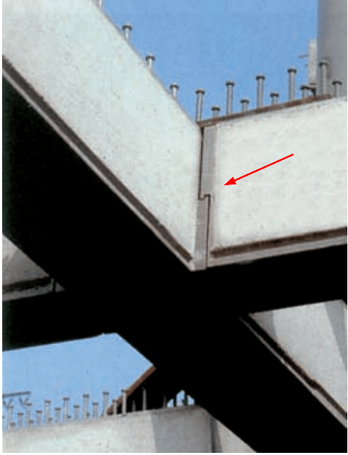
PS: I always supposed that end plates must have the erection gaps, but then once got to the German Museum of Technology in Berlin. Almost all steel girders/beams/joists out there are connected through end plates (most likely hinged). Haven't noticed any large gaps in-between. Might be they are just too small. Will try to recover some of my photos, but they looked some kind like that
2024-01-18_20_03_05-Window_gh6whk.png
 
I've never done a connection like that; it looks too complicated and costly, and difficult to develop a moment if required. If it's a 'snug' fit (not tight) between columns, the shims allow for easier placement. Occasionally (more often than the other) end up with steel being framed into existing steel... and shims are the only way (cost effective way). I typically spec 1/2" max shims, and often spec slip critical. It doesn't affect tensile load for moment, and there is often a surplus in shear capacity.

-----*****-----
So strange to see the singularity approaching while the entire planet is rapidly turning into a hellscape. -John Coates

-Dik
 
SWComposites said:
Why not just ask the steel erector contractor what they prefer?

Yes, sure. This is indeed a best way. Unfortunately not all of them can give a certain answer. Some starting to scratch head and eventually say "We can do everything. Any way will be fine". Most disappointing answer for me
 
When asking the steel erectors preference, are you giving them a specific project or example or just asking about end plates in general? The answer, as it often is in our line of work is "it depends on the situation".

Fabricating a beam to an exact length within 1mm or so is not that difficult. The bigger issue you'll have is over-roll and under-roller tolerances in your columns; they can be slightly deeper or shallower than the theoretical. This is more likely to cause fit-up issues with your doubled end plated beams than the fabricated length of the beam. This is not always an issue. It depends on the size of the building and your erection tolerances. This is often dealt with by letting some columns go out of plumb (within tolerance). This is ok for smaller structures but can be problematic with longer runs of steel and more rigid bracing systems. On larger projects I've seen the rolling tolerances of the columns stack up and create serious fit-up issues with shear tabs and end plates.

To answer your specific question about detailing for this condition. If you anticipate fit-up problems with end plate connections then you should detail it intentionally short. I think your 5mm assumption is a good one for most cases. Don't provide a finger shim that is the same thickness as your theoretical gap. What I'd typically do is if the gap is say 6mm theoretical, I would provide 2 - 3mm shims.
 
In the mechanical world we often design with a nominal shim as part of the assembly.

Then, if things are too tight when you try to put them together, use a thinner shim.

If things are too loose, use a thicker shim.

Pick the nominal thickness based on the process capability, so there will never be a need for negative thickness shims.
 
Thank you all for sharing the valuable opinions and experience! I think I have got now the answer I have looked for.
 
Status
Not open for further replies.

Part and Inventory Search

Sponsor