ErikPSS
Mechanical
- May 16, 2020
- 18
Thank you for the references in past threads -- the paperback introduction by Staniforth was helpful to get oriented, and the Millikens and Gillespie textbooks taught me to find CG, then correctly estimate longitudinal and lateral load transfers, and finally solve for critical damping. I also have a better understanding of this forum and hope to ask general conceptual questions, since I can now check my math against the textbooks.
I would like to ask about guidelines for initially specifying damper force curves. Woods & Jawad (1999) claimed that “dampers are the least well understood suspension components. There does not exist any textbook formulas to produce damper specifications which will ensure appropriate damping characteristics.”
However, the Millikens (1995) gave a sample optimum damping ratio for road-holding of 0.45 for a compact passenger car (p811), with the “coefficient in rebound being about twice that in bump” (p800), while Gillespie (1992) previously noted “typical shock absorbers are dual-rate with approximately a three-to-one ratio between rebound and jounce damping” (p157).
Woods & Jawad concurred: “A 3:1 ratio has historically been considered optimal, and remains a very prevalent ratio” to “help keep the vehicle CG low during corner entry. This is especially beneficial to vehicles with marginal camber control.” They further suggested to “Specify compression damping as a percent of critical wheel damping, say 20-50%” and “Accept values of critical body damping in the range of 70-140%.” They actually used 30% of critical wheel damping for compression damping, and multiplied by 3 for rebound damping.
Matt Giaraffa & Samuel Brisson of OptimumG (2005) gave fairly complex guidelines for damping: an initial damping slope multiplied by 2/3 for low-speed compression and by 1/3 for high-speed compression, and by 3/2 for low-speed rebound and by ¾ for high-speed rebound, resulting in fairly low compression damping as a percent of critical wheel damping and a rebound:compression ratio of 2.3:1.
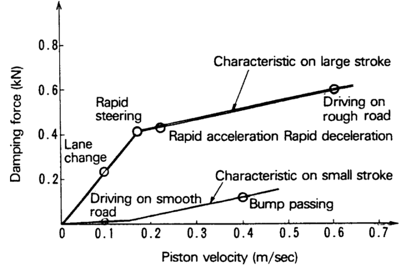
Jim Kasprzak of Kaz Technologies (2012) borrowed heavily (diagrams uncited) from the Millikens, “Non-aero racecars, or those without ground effects, typically use damping ratios between 0.5 and 0.7,” but while he acknowledged that “Most text books recommend a ratio of three to 1, rebound to compression,” he “prefers the compression biased damping on both the front and rear.” Kaz also defines the digression point at 2in/sec.
Dennis Grant of Far North Racing (Autocross to Win) recommended “Set the shocks at 65% critical damping between 0-3in/sec. Somewhere above that, digress the shock off to ~30% critical to handle the occasional high speed whack,” although his calculator works somewhat differently.
Finally, Danny Nowlan of ChassisSim (2013) gave simpler guidelines: low-speed bump damping ratio of 0.5 for a bumpy circuit, with low-speed rebound of 0.5 to 0.7, and high-speed damping of 0.3 to 0.4. Obviously, this results in a very low rebound:compression ratio, but the low- and high-speed compression ratios match Giaraffa and Brisson quite closely.
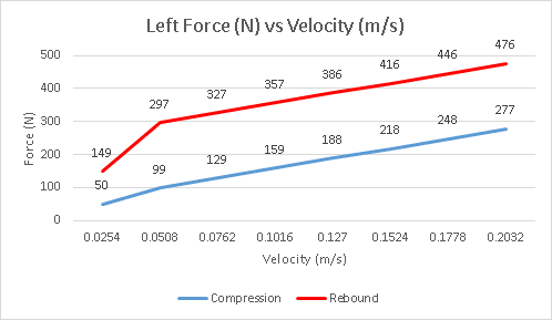
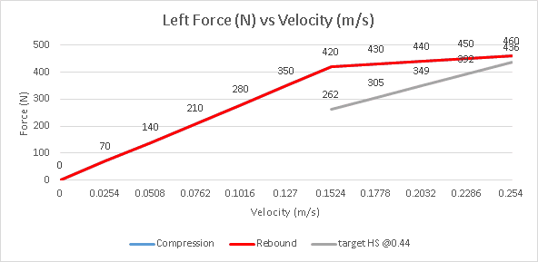
Following this brief survey of the literature, I am specifying the front dampers for a non-aero car with marginal camber control on a bumpy circuit. I am inclined to simply specify low-speed compression damping at 50% of critical, multiplying by 3 for low-speed rebound, then digressing both off at 2in/sec to 30% of critical. However, this leaves compression damping as percent of critical wheel a little low at 25%, and rebound damping as percent of critical body at 150% -- outside the 140% that W&J recommend.

I am curious if anyone can share feedback on any of these guidelines. Thank you in advance.
I would like to ask about guidelines for initially specifying damper force curves. Woods & Jawad (1999) claimed that “dampers are the least well understood suspension components. There does not exist any textbook formulas to produce damper specifications which will ensure appropriate damping characteristics.”
However, the Millikens (1995) gave a sample optimum damping ratio for road-holding of 0.45 for a compact passenger car (p811), with the “coefficient in rebound being about twice that in bump” (p800), while Gillespie (1992) previously noted “typical shock absorbers are dual-rate with approximately a three-to-one ratio between rebound and jounce damping” (p157).
Woods & Jawad concurred: “A 3:1 ratio has historically been considered optimal, and remains a very prevalent ratio” to “help keep the vehicle CG low during corner entry. This is especially beneficial to vehicles with marginal camber control.” They further suggested to “Specify compression damping as a percent of critical wheel damping, say 20-50%” and “Accept values of critical body damping in the range of 70-140%.” They actually used 30% of critical wheel damping for compression damping, and multiplied by 3 for rebound damping.
Matt Giaraffa & Samuel Brisson of OptimumG (2005) gave fairly complex guidelines for damping: an initial damping slope multiplied by 2/3 for low-speed compression and by 1/3 for high-speed compression, and by 3/2 for low-speed rebound and by ¾ for high-speed rebound, resulting in fairly low compression damping as a percent of critical wheel damping and a rebound:compression ratio of 2.3:1.
Jim Kasprzak of Kaz Technologies (2012) borrowed heavily (diagrams uncited) from the Millikens, “Non-aero racecars, or those without ground effects, typically use damping ratios between 0.5 and 0.7,” but while he acknowledged that “Most text books recommend a ratio of three to 1, rebound to compression,” he “prefers the compression biased damping on both the front and rear.” Kaz also defines the digression point at 2in/sec.
Dennis Grant of Far North Racing (Autocross to Win) recommended “Set the shocks at 65% critical damping between 0-3in/sec. Somewhere above that, digress the shock off to ~30% critical to handle the occasional high speed whack,” although his calculator works somewhat differently.
Finally, Danny Nowlan of ChassisSim (2013) gave simpler guidelines: low-speed bump damping ratio of 0.5 for a bumpy circuit, with low-speed rebound of 0.5 to 0.7, and high-speed damping of 0.3 to 0.4. Obviously, this results in a very low rebound:compression ratio, but the low- and high-speed compression ratios match Giaraffa and Brisson quite closely.
Following this brief survey of the literature, I am specifying the front dampers for a non-aero car with marginal camber control on a bumpy circuit. I am inclined to simply specify low-speed compression damping at 50% of critical, multiplying by 3 for low-speed rebound, then digressing both off at 2in/sec to 30% of critical. However, this leaves compression damping as percent of critical wheel a little low at 25%, and rebound damping as percent of critical body at 150% -- outside the 140% that W&J recommend.

I am curious if anyone can share feedback on any of these guidelines. Thank you in advance.


