Continue to Site

Eng-Tips is the largest engineering community on the Internet

Intelligent Work Forums for Engineering Professionals

  • Congratulations cowski on being selected by the Eng-Tips community for having the most helpful posts in the forums last week. Way to Go!

A very simple one!

Status
Not open for further replies.

StoyanAndreev

Structural
Dec 14, 2012
32
Hi, guys! A friend of mine, who is still in the university has this very simple problem to solve with FEA:


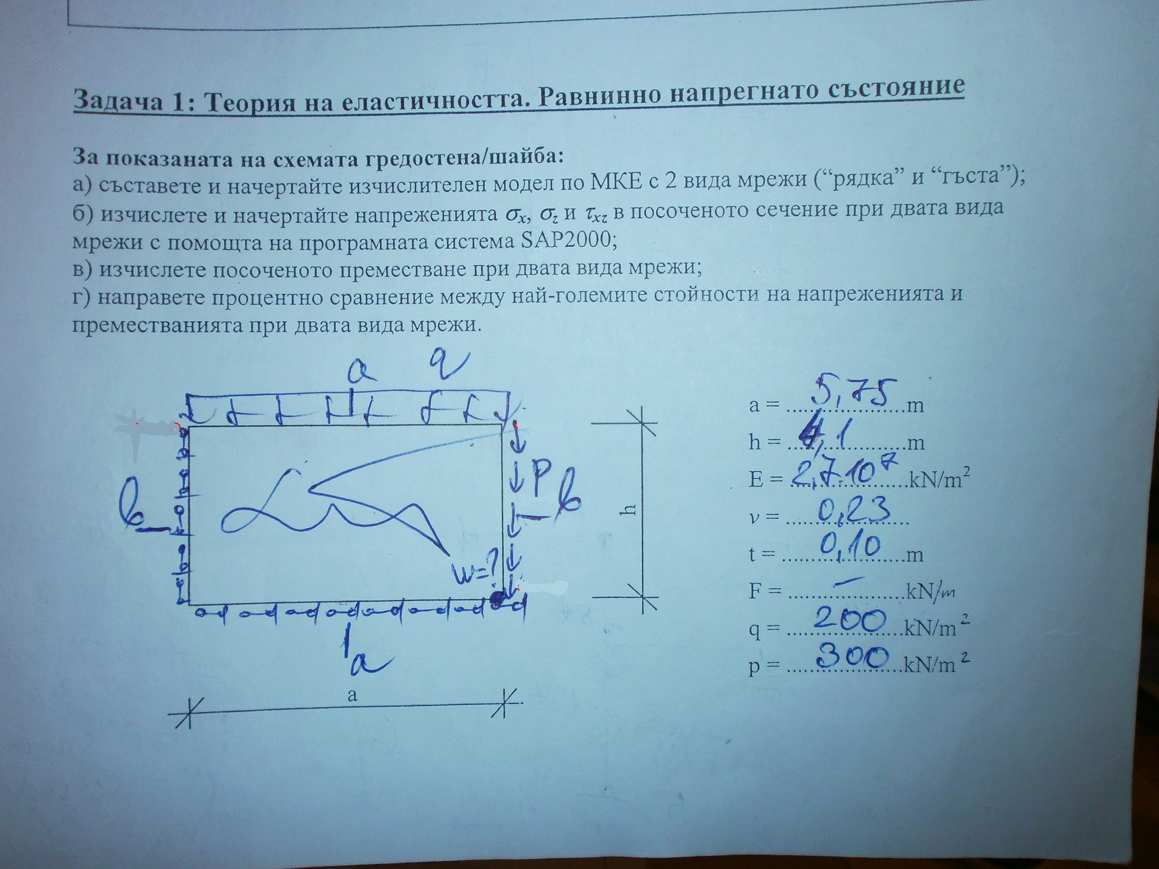
As you see this is a rectangular wall with some uniform edge loads. The problem the girl encountered when analyzing with SAP2000 v.12 was infinitely large displacement of the bottom right node (about 1E+09). I told her that her structure is ill-supported. I also modelled it and I had about the same displacements, so I was sure it is ill-supported. I explained this, but when she went to her assisten professor he told her, that it is absolutely good with boundary conditions - horizontal supports on bottom edge and vertical supports on the left edge). I think I am right, but I want to here some opinions. Thank you!
My Best regards, Stoyan Andreev
 
Replies continue below

Recommended for you

is that because you considered the problem as being in-plane, and didn't constrain the out-of-plane freedoms ?
 
No, it is absolutely in-plane problem - I've tried with full shell elements, membrane-only elements and plane stress elements. It seems that because the two edge restraints have their restrained DOFs intersecting in the bottom left node, the whole structure rotates around this node, because there is nothing to prevent rotation.
 
i understand it's an inplane problem, but you need to constraint all 6 degrees of freedom in FEA even if you know that nothing's happening in those directions.

my russian is a little rusty ... i suspect you're constraining the edges along the edges, or normal to the edge ?

if you are constaining along the edges then you're right, the body is spinning about the lower LH corner. if we were solving by hand we'd ignore this freedom ('cause we know nothing's happening along there). but FE doesn't; and you havn't constrained this freedom. constrain Mz (out-of-plane) at this node, and the displacement will disappear (and your results should not change either, well, at least there'll be no moment reacted by this constraint).

if you are only constaining the edges along the two edges then to properly constrain the model you'll need to constrain Fz, Mx, My, and Mz at the lower LH corner. actually you can constrain there freedoms anywhere on the model and it should solve, but the displacements will be relative to the point controlled (and the lower LH point will give you a more intuitive answer).
 
It is actually Bulgarian, but nevermind. We've used the option in SAP2000 for planar problems - the out-of-plane DOFs are not active anyway, so it is really a in-plane problem. And yes, following the picture, we constrained along the edges, which is the reason it rotates around the left bottom node - and I think that it is a theortical mechanical instability (not only FE), because nothing constraints rotation when we constraint along to intersecting edges. It is a mistake of the guy who drawed the constraints (but he doesn't want to confess he is not right).
 
i was wondering how SAP allowed the run to work.

constraining along the edges does not constrain in-plane rotation (clearly).

if someone doesn't want to admit they're Wrong, let them live in their own world.
 
Some time ago (4,5 years ago) I had my first steps in FE with SAP2000. Back then they didn't allow this - in cases like that the message was simply ill-conditioned structure. But I think in recent versions for numerical stability they introduced some very small numbers in case of singular stiffness matrix (as it is in many other codes) and that's why the calculate displacements with magnitude 1E+09 (they have a really close to but actually not a singular stiffness matrix). Thank you very much for this conversation, I appreciate this. Have a nice weekend!
 
i wondered about this problem ... is the panel supposed to be in pure shear ? the hand drawn arrows don't make it look that way ... on the top edge they should point to the left. but then the problem doesn't look that way ... p:q is not equal to b/a. the point, if it is a pure shear panel, then there'll be no out-of-plane moment in the real world (though you'll still need to constraint it in the FE world).

looking at the problem again ... both the applied forces are drawn in the y-direction, but i understood that the reactions were along (not normal to) the edges ? if loading is all in the y- direction then i'd expect to see no net load in the x-direction (on edge "p"); in the model world ther would be balancing reactions if you constraints prevent poisson displacements . this is enough to say that the reactions on both edges are generally in-plane ... along and normal to the edges; this way a couple of x-forces will react the Mz moment due to the loading.
 
Status
Not open for further replies.

Part and Inventory Search

Sponsor