Eng-Tips is the largest engineering community on the Internet

Intelligent Work Forums for Engineering Professionals

A10VSO Variable displacement pump power control

Status
Not open for further replies.

simran1983

Industrial
Aug 21, 2015
12
0
0
IN
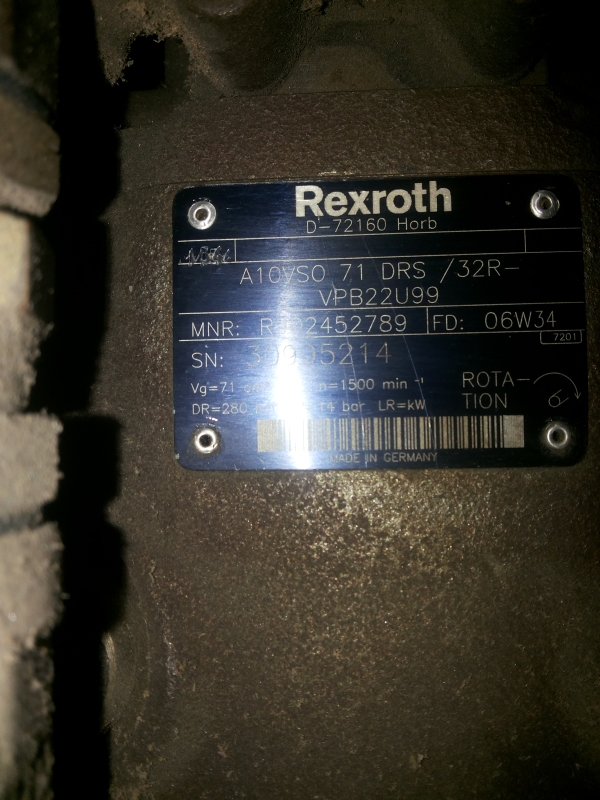
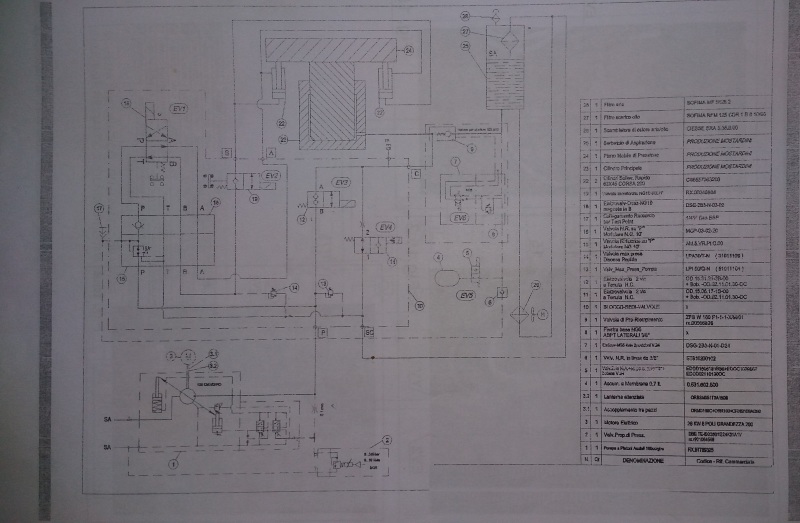
I am maintaining a hydraulic press which is having a piston of 600 mm. It works up to 280 bars and creates a maximum force of 800 Tons. It is having a Rexroth A10VSO 71 DRS/32 pump which delivers 100 lpm of oil at 1440 rpm. It is coupled with a 35 HP electric motor. Please find attached images of the pump and also the schematic of the hydraulic circuit.

Pump
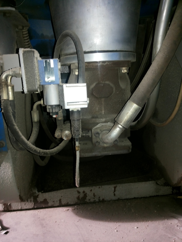
20140911_160740_gnlch2.jpg


Pump's name plate
20140911_160807_proqyi.jpg


Hydraulic Schematic
20151114_203310_pinoow.jpg


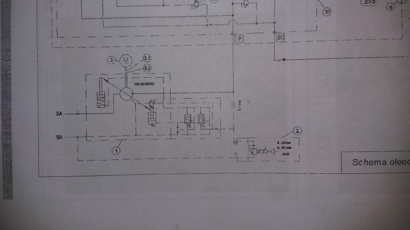
Pump's Control Circuit Zoomed
20151114_203318_nypmwa.jpg


**********************************************************************************
(These are the links to the images in case they don't open up in the post directly)

view

view

view

view

**********************************************************************************

Now my problem:

By looking at the schematic, it suggests the pump to be a power control pump (i.e DFLR in terms of Rexroth’s terminology). But physically (see the image attached) it is NOT a power control pump. Practically, power control is taking place in the circuit - otherwise a pump delivering 100 lpm of oil cannot go up to a pressure of 280 bars with a 35 HP Motor. My question is how power control is taking place in the circuit?

The manufacturer has installed a proportional relief valve (Rexroth DBETE) in the pilot line of the controller. In the machine’s manual it says that by varying the pressure setting of this valve, the flow of the pump can be changed. Again, my question is how is it happening?

As far as I know (and as Rexroth’s product manual says) the flow of A10VSO 71 DRS/32 can be dynamically changed by creating a pressure drop across a variable orifice in the delivery line of the pump. But I don’t see any variable orifice in the circuit. If the flow is dynamically controlled, then power control can be achieved. But, in this circuit, how is flow being dynamically reduced with the rise is pressure so as to achieve power control.

Please help me out. Thank you.
 
Replies continue below

Recommended for you

It's a load sensing pump and it senses the pressure difference across the, what looks to be, the 6.1mm orifice. The one just to the right of the pressure cut off and LS compensators on the drawing.

The proportional pressure relief valve (Item 2) opens at the set pressure. When opening, the flow across the orifice increases, the pressure drop goes up, the LS compensator responds to the difference. At this point, the pump will back off or increase its displacement to maintain the pressure drop over the orifice.

In this respect, the pumps is dynamically controlling flow, against changing pressure, to give constant power control.

Cheers

Adrian

Adrian Wright CEng MIMechE
Engineering Specialist
Hydraulic Systems
Caterpillar (UK) Ltd
 
Hello,
You are right, the proportional valve 2 thus limits the maximum pressure force up to 800 tons.

For me two solutions:
a) The name plate does not correspond to the pump scheme. The pressure relief valve designed on the pump rate decrease piston is it not a representation of a power control?
b) There is no integrated power regulation at the pump: It is not uncommon on a press or shears we spend 2 times the rated power of the electric motor for a short time. 100l / min at 280bar this gives 52kW to the shaft of the electric motor.

Greetings
 
The pump part number and controller matches what is shown on the drawing. The press manufacturer has simply adapted the control to make it more efficient and to allow a smaller motor.

Is there a problem with the current operation or are you just trying to understand what's happening?

Cheers

Adrian
 
Thanks for the replies friends. But the concept is still  not clear to me. The pumps name plate says DRS.  That means it is a flow control model with X to T line plugged. Now as Adrian says, the manufacturer has adapted the control to work like a power control. This is what I am not quite clear.

Power will be automatically controlled if we can control the flow dynamically. In a DRS control, the pumps entire flow passes through a variable orifice which creates a pressure drop.  When this happens, the flow controller shifts and gives oil to the back of the yoke piston.  This in turn reduces the flow of the pump . As a result the pressure drop is also reduced. This keeps on happening (the flow gets reduced) until the pressure drop is equal to the spring setting of the DRS control.

The spring of the controller now again tries to increase the flow but the resultant pressure drop again reduces the flow.  The spool modulates to maintain the flow at a required level, say 65 lpm. This is how flow control takes place in a DRS control. Correct me if I am wrong here Adrian.

As  I had stated in my original post that the machine manual says that by varying the pressure setting of the proportional valve (item 2), the flow can be changed.  The actuator will move with different speeds. Now can you explain me (just as I did in the DRS control) how this is happening with a proportional relief valve.  How does the pump maintains is flow level.

I think if we can understand this,  then power control will be automatically understood.

Waiting for your valuable suggestions please.
 
Look at the orifice...

You can see that the pump load sense compensator is looking at pressures on either side of the orifice.

When you first start the pump, the pressure at the outlet is what the load sense compensator is set to. The strategy of the pump controller is to always maintain that pressure. It is usually around 1500 - 2000 kPa.

The delta pressure at the compensator will be the same as the pressure drop across the orifice.

By opening the proportional valve, the flow rate at a particular pressure can be set.

Remember that the pump is always trying to maintain the pressure drop across the orifice. In this case, rather than having a variable orifice, the flow is being varied instead. The result is the same, the pressure changes.

So, in order maintain the pressure drop, the pump will increase or decrease the flow rate. This is done by supplying oil to the servo piston. The pump moves the swash plate until it gets the pressure drop it needs.

The name plate on the pump is correct, it's a DRS controller. The only difference is as I say, there is not variable orifice. To change the pressure drop, the proportional valve opens to change flow and pump responds accordingly to maintain flow.

The flow from the pump is directed to the actuators, but the pump control remains independent of the load at the actuators. In this way, you are able to maintain power control independent of load.

It's an elegant solution, it works and the pump name plate is correct. You'll agree once you understand how a load sensing pump works.

Just remember, the control strategy of the pump is to maintain the pressure drop across the orifice. If the proportional valve moves to change the pressure...the pump will change the flow to compensate.

As always, if it's not clear...please don't be afraid to ask.

Cheers

Adrian

 
Attention to "HPost": I am like simram1983, I do not understand the explanation. Could you give us the signal values proportional pressure relief valve according to the desired flow rate at the pump?
 
I cannot give any values for command signals etc...

I can only explain the principle of operation with information available at this time.

If we can confirm the diameter of the orifice, we can calculate the pressure drop when the pump is at full stroke, then start to look at what flow area would be needed through the proportional valve.

It would also help to know the stand by pressure of the pump

Adrian
 
It's a power limiting pump with a load sense compensator. However the LS compensator is only being used to enable the proportional relief valve to adjust the cut-off (maximum) pressure. The 1mm (not 6.1mm) orifice is simply to feed the proportional relief valve.

The power limiting is achieved with the pilot relief valve closest to the pump. As the control piston extends to de-stroke the pump it also increases the pressure setting of this pilot relief (usually a dual spring arrangement to approximate to a hyperbolic constant power curve). So with a reduced flow the pump is allowed to go to a higher pressure thus keeping within the power limit. The initial setting of this pilot relief thus determines the power limit and the setting of the proportional relief sets the normal cut-off pressure.

The ultimate cut-off pressure can still be adjusted manually by means of the pressure limiting compensator spool (the left hand one).
 
Once again .. Thanks a lot for he replies. Sorry for such a late reply - just joined work again -- was hospitalised..

Well Adrian.. you are correct. I agree with your explanation. You said "It's an elegant solution, it works and the pump name plate is correct. You'll agree once you understand how a load sensing pump works" .. that's correct. I found a document of Parker, explaining the same load sense control in each stage. Am sharing the pdf file here.


Thanks once again for clearing my concepts !!
 
Hello...

I am sorry to hear that you have been in hospital, I hope you are better now. Your health is much more important than how this stuff works.

I am glad to help I am glad that the help has been worthwhile.

Good luck!!!

Cheers

Adrian
 
Hello Simran and Adrian,

I am in Europe and works on power units with pumps flow rates from 850 to 4680 l/min at 350bar. Obviously the electrical or thermal engines may issue area power. And so I strongly would be interested to understand how you make the other side of the Atlantic Ocean to use pumps without power control. It could be saving a lot to the design.

Simram: you write "In the Machine's manual says it that by varying, the pressure setting of this valve, the flow of the pump can be changed".
Could you give me details on this phenomenon? Do you have a possibility of changing the current to the DBETE? When you change the setting, do not you have a always the same fast speed with no load and a different pressure increase speed? Do you have a closed loop electronic control which measures the intensity of the electric motor or the pressure multiplied by the speed of the cylinder?
 
Hello...

Actually, I'm in England.

The relief valve is a proportional valve, so the valve setting is changed by adjusting the current to the coil.

Yes, as the setting is changed, the pump will respond by increasing or decreasing the flow and so the cylinder will speed up or slow down accordingly.

There is usually no need to have a closed loop on applications like this, but it is possible to have pressure or flow feedback or both to give better control or more precise power control.

Cheers

Adrian
 
Sorry but I beg to differ.

It's a power limiting control with proportional adjustment of the maximum pressure as per my earlier post.

The pump delivers maximum flow until the pressure increases to a level where the power limit is reached. The pump will then reduce its flow as the pressure increases further to remain approximately within the power limit set. Although it's using a load sense compensator, then is no load sensing taking place.
 
Bumblyari is quite correct, it is a subtle adaptation of a load sensing compensator to give power limiting.

Hey ho, at least some people learnt a little about load sensing.

Sorry!!!

Adrian
 
I have had a closer look and the following is what "should" be happening. Please note that the original pump with am LAXDS controller shown in the drawing may have been replaced with a similar pump with a DRS controller.

The LAXDS controller has an additional relief that is attached to the pump servo piston to give constant power or constant torque. That controller is not visible on the pictures, which makes me think that the pump may have been swapped.

The principle of the LAXDS controller is to give flow control below the max power/torque curve. This is achieved as described above, by sensing the pressure drop across the 1mm orifice.

The LAXDS and DRS compensators are very similat, both have a margin compensator and a pressure cut off compensator. The margin compensator should be set to 15-20 BAR and when the proportional valve is switched off, there is no pressure on the "x" port and so the pump will sit at the standby pressure.

The cut off compensator will be set to give the maximum pressure. In this case 280 BAR, which happens to be max working pressure of the A10 pumps.

When valve EV3 opens to move the press, the pump outlet pressure would drop and oil would start to flow, but while the delta pressure over the 1mm orifice is higher than the margin compensator setting, the pump flow will remain low. This is where the flow control works. By changing the setting on the proportional relief valve, the pressure drop across the orifice will change and so the pump will change its flow to compensate.

Power and torque are both a function of pressure x flow rate (displacement). The torque limiter works by sensing the servo piston / swash plate to increase the allowable pressure. As the swash plate moves to reduce flow it increases the cracking pressure of the relief valve, so as flow goes down, pressure goes up and vice versa, as flow goes up, the max pressure comes down. Either way, it gives constant power and below that power curve, the flow control is infinitely variable by controlling the current to the proportional valve.

As drawn the system gives Power, Pressure and Flow Control. However, the pictures do not tell the same story.

So whilst I agree that the pump has power control, the flow and pressure control are as described above. It's essentially a load sensing system with a power limiter on top.

It may help to supply some pictures of the other other side of the pump. To see if there is a power limiting valve attached to the servo piston.

Cheers

Adrian

 
I agree that the load sense pump in the picture does not appear to be the same as the power limiting one on the circuit.

However the circuit diagram describes a power limiting pump with proportional control of the cut-off pressure ie. no flow control. This is a standard method of achieving remote or proportional pressure limiting when the pump doesn't have a two-stage compensator.

Depending upon what the press is doing depends what type of control is most suited. If it's a gradual squeeze (like a baling press) then the power limit control is useful (to speed up the cycle time). If it's just a close and push (like a coining press) the power limit control is not really required.

It's not necessary to operate EV3 to close the press as it is closed by the two kicker cylinders on either side via EV1. The main press cylinder fills via the prefill valve (sorry can't read its number). Only when the final squeeze is required does EV3 energise which leads me to think that its working stroke is relatively short and so power limiting would not be a big advantage.
 
So you are saying that both compensators that are on the drawing and visible in the pictures are actually not working?

Even though the pump supplier's description that matches the schematic diagram, that also describes the operation as being flow and pressure control, with power limiting...that's all wrong too? I can't see that being the case.

It's not worth arguing about, it's educational...
 
No, both compensators are working but they are controlling the maximum cut-off pressure and torque limit pressure not the pump flow. The proportional relief valve enables the cut off pressure to be set electronically. The pump flow will of course reduce when the pump power hits the power limit curve but the pump flow is not directly controlled by the proportional relief.

Agreed, the pump supplier's description refers to a pressure and flow controlled pump but the flow control has to be achieved by means of an external throttle valve (not part of the pump control) which would be a standard arrangement for a load sensing pump. However, there is no such flow control in the press circuit but the load sense compensator is being used for the proportional adjustment which as I said is a common arrangement. There is no load sense line coming from the press cylinder and when EV3 is energised there is nothing between the pump and the press cylinder other than a straight-through piece of pipe, so no flow control.
 
Status
Not open for further replies.
Back
Top