simran1983
Industrial
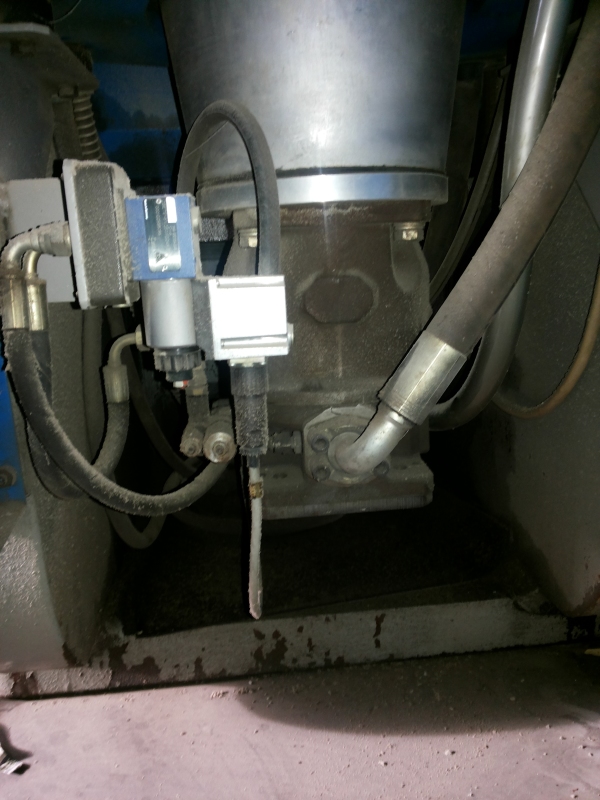
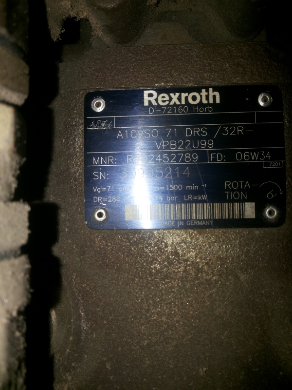
I am maintaining a hydraulic press which is having a piston of 600 mm. It works up to 280 bars and creates a maximum force of 800 Tons. It is having a Rexroth A10VSO 71 DRS/32 pump which delivers 100 lpm of oil at 1440 rpm. It is coupled with a 35 HP electric motor. Please find attached images of the pump and also the schematic of the hydraulic circuit.
Pump
Pump's name plate
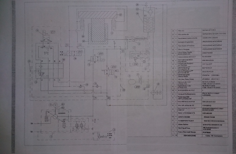
Hydraulic Schematic
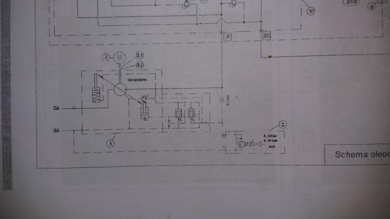
Pump's Control Circuit Zoomed
**********************************************************************************
(These are the links to the images in case they don't open up in the post directly)


**********************************************************************************
Now my problem:
By looking at the schematic, it suggests the pump to be a power control pump (i.e DFLR in terms of Rexroth’s terminology). But physically (see the image attached) it is NOT a power control pump. Practically, power control is taking place in the circuit - otherwise a pump delivering 100 lpm of oil cannot go up to a pressure of 280 bars with a 35 HP Motor. My question is how power control is taking place in the circuit?
The manufacturer has installed a proportional relief valve (Rexroth DBETE) in the pilot line of the controller. In the machine’s manual it says that by varying the pressure setting of this valve, the flow of the pump can be changed. Again, my question is how is it happening?
As far as I know (and as Rexroth’s product manual says) the flow of A10VSO 71 DRS/32 can be dynamically changed by creating a pressure drop across a variable orifice in the delivery line of the pump. But I don’t see any variable orifice in the circuit. If the flow is dynamically controlled, then power control can be achieved. But, in this circuit, how is flow being dynamically reduced with the rise is pressure so as to achieve power control.
Please help me out. Thank you.
Pump
Pump's name plate
Hydraulic Schematic
Pump's Control Circuit Zoomed
**********************************************************************************
(These are the links to the images in case they don't open up in the post directly)
**********************************************************************************
Now my problem:
By looking at the schematic, it suggests the pump to be a power control pump (i.e DFLR in terms of Rexroth’s terminology). But physically (see the image attached) it is NOT a power control pump. Practically, power control is taking place in the circuit - otherwise a pump delivering 100 lpm of oil cannot go up to a pressure of 280 bars with a 35 HP Motor. My question is how power control is taking place in the circuit?
The manufacturer has installed a proportional relief valve (Rexroth DBETE) in the pilot line of the controller. In the machine’s manual it says that by varying the pressure setting of this valve, the flow of the pump can be changed. Again, my question is how is it happening?
As far as I know (and as Rexroth’s product manual says) the flow of A10VSO 71 DRS/32 can be dynamically changed by creating a pressure drop across a variable orifice in the delivery line of the pump. But I don’t see any variable orifice in the circuit. If the flow is dynamically controlled, then power control can be achieved. But, in this circuit, how is flow being dynamically reduced with the rise is pressure so as to achieve power control.
Please help me out. Thank you.