Continue to Site

Eng-Tips is the largest engineering community on the Internet

Intelligent Work Forums for Engineering Professionals

  • Congratulations KootK on being selected by the Eng-Tips community for having the most helpful posts in the forums last week. Way to Go!

AASHTO code provisions related to second order moments

Status
Not open for further replies.

Hassaan_16

Structural
Apr 19, 2022
14
Hi! A complete novice here. I'm designing a bridge pier (L=26m, D=1.8m, laterally braced at mid-height. Using CSI Bridge). I was analyzing the design data when I saw that the value of Delta_b (Moment magnification factor for non-sway moments) was 2.093. I know that the ACI 318 limits the non-sway moment magnification factor to not more than 1.4 but the software didn't generate a warning message when designing using the AASHTO LRFD 2014 code. So, I designed the pier again using ACI 318-19, and as I expected, the software generated a warning message saying that the Delta_ns (Delta_b in the case of AASHTO LRFD) exceeded the maximum value of 1.4 (Delta_ns=1.489) and declared the member as "Over stressed" (O/S). Please guide as to what should be done in this case when one code is passing the pier section while the other declares it as over-stressed. TIA..
 
Replies continue below

Recommended for you

Bridge piers are designed per AASHTO, and AASHTO, as far as I know, does not limit the moment magnification factor. It does limit the slenderness ratio where the moment magnification is applicable, but as long as you're under that limit, the properly calculated moment magnification is applicable.

When you say that the pier is braced at mid-height, do mean there is diagonal bracing, or that individual columns are connected to other columns? If you've entered the full pier configuration into CSI Bridge, it will determine the bracing condition. However, just connecting 2 columns together, when they can both buckle, should not be considered a braced condition.

Rod Smith, P.E., The artist formerly known as HotRod10
 
Thanks BridgeSmith for your reply and sorry for delay in my response.
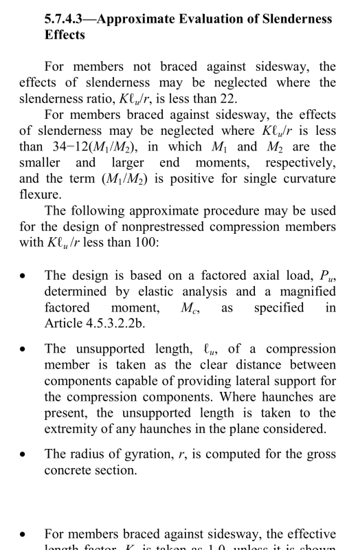
First, when you say that AASHTO limits the slenderness ratio, are you indicating towards the "klu/r<100" clause?
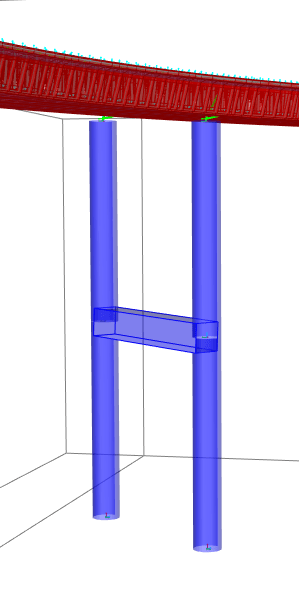
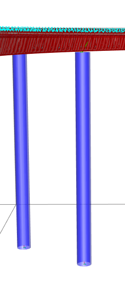
Secondly, to answer your question, by bracing I mean that the piers are simply connected via a bracing beam to restrain the individual piers against buckling. I know this isn't a braced condition but the objective was to reduce the unbraced length and to improve the buckling load capacity of each pier. I'm attaching the snippets of both models (With and without bracing beam) as well.

slenderness_uxnfmn.png

braced_piers_q669rh.png
unbraced_piers_m96ppr.png
 
First, when you say that AASHTO limits the slenderness ratio, are you indicating towards the "klu/r<100" clause?

Yes. I've never used CSI Bridge, but I would assume it would not use the moment magnification, but it's performing an FEA to calculate the moments.

The midheight bracing should increase the capacity from what the unconnected columns would have, but then the 'global' failure mode of both columns buckling should be considered. If properly modeled, the structural analysis in the software should capture that behavior.

It's likely buckling in the other direction will control the axial capacity.

You can limit the moment due to eccentricity by setting realistic boundary conditions for the displacement at the top of the columns, based on how much movement is allowed by the connection to the superstructure and the lateral movement/deformation of the superstructure.


Rod Smith, P.E., The artist formerly known as HotRod10
 
I dont really know well CSIBridge, but sometimes use SAP2000. SAP2000 has a some kind fuzzy logic that cant detect and input K, or Lateral braced length automatically.
Most software had user to input K, Lminor, Lmajor, L braced torsional, L braced length for properly compute design code AASHTO/ACI after FEA computing finish, like Staad, Midas/Civil, Lusas, etc.
The software will computer moment magnification automatically it self by compare moment by vertical load case and lateral sway load case, however you need input K, Lz,Ly correctly or buckling will failed to computer correctly.
Since you have circular column it has same radius gyration all direction.
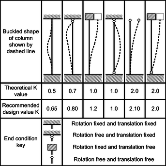
The one without mid lateral bracing, assuming you have free bearing on the top ( girder just have vertical loads and not locked on both ways lateral and long ) you will had input K=2.1 and Ly Lz as total height column. If you had guided but fix in lateral then the K lateral can be 0.8, while the K long is 2.1. If you had fixed long bearing, it can be assumed that top pier has pin fixity and all K = 0.8

If you had middle lateral bracing than the lowest column will be Klat =0.85 Klong = 2.1 with L lat= height low column, and L long = Total pier height
The top column assumed as free bearing then K lat = 2, K long 2.1 with L lat = top column and L long = Total pier height.
For other fixity at top column the K and the L will vary.

As Rod said, the column will have minimal capacity due buckled to the long direction, where the lateral braced significantly reduce lateral buckling.

ColumnEffectiveLength_lnaces.png
 
Status
Not open for further replies.

Part and Inventory Search

Sponsor