Eng-Tips is the largest engineering community on the Internet

Intelligent Work Forums for Engineering Professionals

  • Congratulations waross on being selected by the Tek-Tips community for having the most helpful posts in the forums last week. Way to Go!

AASHTO Spiral Reinforcing Area

Status
Not open for further replies.

bpiermat

Structural
Mar 7, 2006
44
0
0
US
Hi,
I need a quick thought on this design approach.
In the current AASHTO 8th Edition, the formula for calculating minimum transverse steel and for calculating member shear capacity due to transverse steel depends upon the value Av or Area of Transverse Steel. What is the appropriate value to use here for Spirals? Here are some choices... 2 * A, pi/2 * A or just A. Where A is the area of a single hoop bar.

Thanks!
 
Replies continue below

Recommended for you

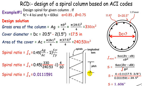
Haven't designed circular column for a long time, as far as I can remember, the design of spiral reinforcement involves the calculation of reinforcing ratio for a given configuration of the column (known column diameter, clear cover) using code equation. Then calculate the trial pitch (spacing) using proposed bar cross sectional area (As) and code equation. I think As can be considered Av, but a single leg only.
 
A[sub]sp[/sub] is defined as "cross-sectional area of spiral or hoop", so the area of the bar, in the calculation of the reinforcement ratio.

For calculating shear capacity, it's the total area of the bars crossing the shear failure plane. Therefore, it would be 2 * A[sub]sp[/sub], because the failure plane intersects the spiral twice for each space, just as you would count both legs of a stirrup or tie.

I should add that I've never had to think about the shear capacity calculation, since every column I've ever designed had more than adequate shear capacity using the concrete alone.

Rod Smith, P.E., The artist formerly known as HotRod10
 
AASHTO could be different. I think ACI was using "volume metrics(?) method" instead of direct design for variation in shears. What are the steps and equations for the design of spiral reinforcement?

If circular stirrups (hoop) are to be used, then I would agree there are two legs in the shear plane, the same as the design of rectangle stirrups.
 
If circular stirrups (hoop) are to be used, then I would agree there are two legs in the shear plane,

It's the same for spirals. Draw a column with a spiral. Now slice through the column at a 45[sup]o[/sup] angle and see how many bars the slice goes through. I think you'll find it's the same as it would be for hoops or ties at the same spacing as the pitch of the spiral.

Rod Smith, P.E., The artist formerly known as HotRod10
 
Here is a design example. I think AASHTO does use other method I don't know.

spiral-reinforced-column_zcenqb.jpg
 
AASHTO uses the same calculation for the reinforcing ratio (volumetric ratio), retired13, and limits the minimum and maximum ratios calculated per those equations. The calculation for Vs (contribution of shear reinforcement to the shear capacity of the section), however, is based on the area of reinforcing steel crossing the assumed shear failure plane.

Rod Smith, P.E., The artist formerly known as HotRod10
 
Rod,

Thanks for bring up the correct name of this method, yes, "volumetric" . I don't recall the limits on the applicability of using spiral reinforcement, but the beauty of this method is that, if permitted, after calculating the reinforcing ratio, by plug in a trail/desired As, the required spacing is thus determined. The shear force is no where in the design process, is it?
 
The prescriptive requirements for the volumetric ratio of reinforcement, required to confine the concrete core in flexure, are separate from the shear capacity provisions. Both are design requirements, but for different aspects of the design.

Rod Smith, P.E., The artist formerly known as HotRod10
 
Column compressive design strength is permitted to be higher when spiral reinforcement is provided (Ø = 0.75, vs 0.7 for hoop reinforcement), but no change in flexural (Ø = 0.9, spiral or hoop). Because shear is caused by compressive force, but it is kept in check when the compression area is well confined. Both (spiral and hoop) are shear reinforcement. You need to judge the type of shear reinforcement is suitable for your application, then follow through the method prescribed by code using proper parameters.

Columns support primarily axial load but usually also some bending moments. The combination of axial load and bending moment defines the characteristic of column and calculation method. A column subjected to large axial force and minor moment is design mainly for axial load and the moment has little effect. A column subjected to significant bending moment is designed for the combined effect. The ACI Code assumes a minimal bending moment in its design procedure, although the column is subjected to compression force only. Compression force may cause lateral bursting because of the low-tension stress resistance. To resist shear, ties or spirals are used as column reinforcement to confine vertical bars. The complexity and many variables make hand calculations tedious which makes the computer-aided design very useful.
 
WDOT said:
7.4.5 Transverse Reinforcement
A. General – All transverse reinforcement in columns shall be deformed. Although allowed in the AASHTO LRFD Specification, plain bars or plain wire may not be used for transverse reinforcement.

Columns in SDCs A and B may use spirals, circular hoops, or rectangular hoops and crossties. Spirals are the preferred confinement reinforcement and shall be used whenever a #6 spiral is sufficient to satisfy demands.
 
Status
Not open for further replies.
Back
Top