Continue to Site

Eng-Tips is the largest engineering community on the Internet

Intelligent Work Forums for Engineering Professionals

  • Congratulations MintJulep on being selected by the Eng-Tips community for having the most helpful posts in the forums last week. Way to Go!

Abaqus - Basic Operations Help

Status
Not open for further replies.

VN1981

Aerospace
Sep 29, 2015
186
It seems like I am having issues with what I consider are basic operating features of any FEA package.

To start with, I am not able to delete quad elements from a mesh. I created a shell (plate) with 0.1" thk and assigned it a simple 4-node shell quad element. I have defined the Assembly Instance as Defined. When I try to delete an element from Mesh->Edit->Element->Delete, I get the following error.

Ab_01_nqybft.png


The manual says that I am supposed to get a Mesh Edit menu with more options. Somehow Abaqus is not presenting me with such an expanded menu.

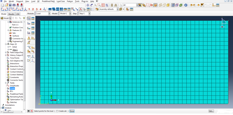
Secondly, If I want to apply a Concentrated Point Force on a node via GUI i.e. Abaqus CAE, how do I achieve it? All I get is an option to chose points. Again I read in another thread that I am supposed to get an icon where I can select to apply it on nodes.
Ab_02_yo42ku.png


Lastly, I had asked this question in a different thread. Asking it again here. I have applied a shell edge load of 40 lbs/in. This model is simple and thus I can calc the total load & moment. Is there an utility to check value of total external loads in Abaqus before submitting it for analysis?

Thanks in advance...
 
Replies continue below

Recommended for you

Hey,

I can only help you with the second question. You should create a set in your part first (expand "part" in the menu and double click "sets" ). Make it a node set and chose the node you want to apply the cforce on later. The you go to loads and when you are at the Point of your second Picture, you press the "Sets..." button on the bottom right of the window. Chose your set, and then chose the value and direction of your force.

Greets
 
Thanks keulehans for the reply.

I was able to discover the said procedure you have mentioned. Unfortunately, it seems like Abaqus CAE currently does not allow CForce loads to be applied directly over the nodes of native mesh.

I was doing a stiffened panel analysis subjected to an uniform axial tensile load and again Abaqus does not allow node offsets for L shaped Beam Elements, which I find it strange. It does allow node offsets for I, Hat and Trapezoidal ones. I overcame the problem by offsetting the shell element and now I have unwanted moments in the shell. Of course, I can constrain the shell elements against out of plane bending but I would have preferred to offset the beam elements rather than shell.

I am still surprised that a popular package doesn't have a tool to check summation of total external loads & moments acting on the structure.
 
You said "I have defined the Assembly Instance as Defined". This doesn't make sense - do you mean dependent/independent?

The only way I can replicate your problem is by creating an independent instance that I mesh at the instance level. If I create a dependent instance and mesh at the part level I can access all of the mesh editing options described in the users manual. I can also apply concentrated forces directly to any nodes which I can select using the UI when I create a dependent instance (I cannot do this with independent instances). To apply forces directly to nodes in CAE you need to define a node set or create your instance using a mesh part.

As to your final point, you can extract/sum whatever forces you want from an analysis.

 
Folks,
Any good tutorials on advanced post-processing in Abaqus CAE?

I did a simple stiffened panel analysis, representing stiffeners using 1D beam elements and skin using 2D shell elements (Quad). I find that I am not able to obtain results of the entire structure together. Like Abaqus displays results of either shell or Beam elements one at a time. Is this a limitation?

I feel like a good post-processing tutorial will answer many of my questions. Would appreciate experienced users pointing out to the same.

Thanks
 
The learning curve on Abaqus CAE is slightly more steeper than I expected!

I discovered that, it is not possible to merge coincident nodes of an Assembly. Kinda makes sense...but if you have a situation where different components are in contact with each other but inclusion of Contact in analysis is not desirable, then one has to create a new Part or meshed Part using Merge option from Assembly and merge nodes. A little convoluted...

The other question I had is default results orientation in Abaqus. If I've understood it correctly, the default shell and beam elements results orientation is wrt local element coordinates and not Global CSYS, correct?

Also in Post-processing, is there any way to include only a certain sets of elements or nodes in contour output? I don't see any option of selecting sets either.
 
Status
Not open for further replies.

Part and Inventory Search

Sponsor