Eng-Tips is the largest engineering community on the Internet

Intelligent Work Forums for Engineering Professionals

Abaqus-CAE : Circular footing soil as Spring

Status
Not open for further replies.

shubbad

Structural
Sep 25, 2023
21
0
0
IN
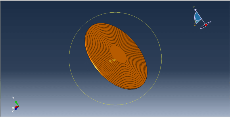
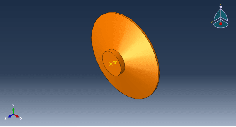
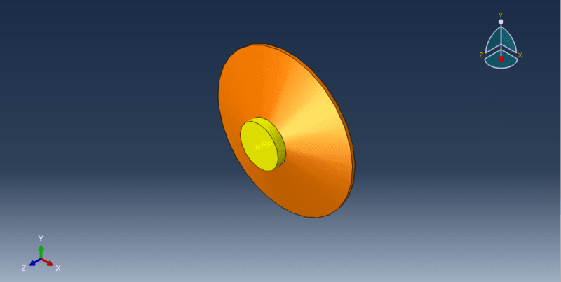
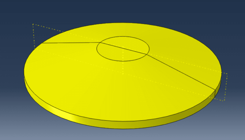
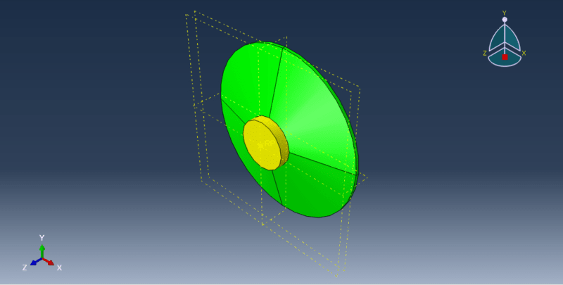
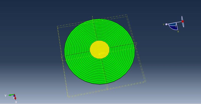
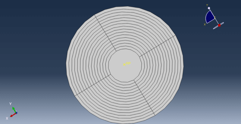
"I have modeled the wind turbine foundation. I have modeled the soil as a spring and applied vertical load, horizontal load, moment, and non-uniform pressure using Analytical field and gravity load. For the spring, I have set the stiffness using a connection to the ground (Standard) with DOF = 3. However, when I am running the model, it is showing an error. I have asked someone, and they are telling me it is not converging due to an equilibrium error, but I don't know how to correct it." I am using Abaqus Software for the Analysis.
 
 https://files.engineering.com/getfile.aspx?folder=3011767c-335f-497b-b6f0-a34d3a3f753d&file=Screenshot_2023-09-25_222221.png
Replies continue below

Recommended for you

so you've modelled the soil as a bunch of springs, resisting force in all directions. These springs connect the model to the ground, so a node is on the wind turbine, and the other node is the ground. You constrained these ground nodes, yes ?

"Hoffen wir mal, dass alles gut geht !"
General Paulus, Nov 1942, outside Stalingrad after the launch of Operation Uranus.
 
When we are selecting the connection to the ground (standard) then we have to select the node of the foundation only and then we have to assign the stiffness value and DOF. There is no need of constraining it.
 
You have a spring in the third direction but what about the other directions ? Are they unconstrained ? This will lead to rigid body motions.
 
Actually, it is a circular footing resting on soil. The soil is modeled as a spring, which is why I applied the spring only in that specific direction, leaving all other directions unconstrained. However, I'm encountering an equilibrium error while running the analysis. Please provide guidance. How can I counter rigid body motion, and what modifications do I need to make? Please provide guidance.
Thank you.
 
You should add springs in the remaining directions (with low stiffness - just to avoid underconstraint) or use a boundary condition fixing displacements in those directions.
 
Okay sir, I will add the spring in the remaining direction and will let you know. Can you please explain the second thing, "by fixing the displacement in those directions " I didn't understand this. What it actually means?
 
I'm talking about the displacement boundary condition set to zero for those remaining directions. But in your case, low-stiffness springs might be the best option.
 
I had read the OP as saying he was constraining the soil in all three directions.

if we're dealing with loads in a single direction (3) then this also reacts M1 and M2, yes?
then to constrain rigid body motion we need three more constraints, either 2*(1) and 1*(2) or 1*(1) and 2*(2) to react the remaining three dof ... (1), (2), and M3.
if we have have 1 (2) rigid constraint, and 2 (1) constraints (offset so the react M3) then we react the req'd directions, yes?

"Hoffen wir mal, dass alles gut geht !"
General Paulus, Nov 1942, outside Stalingrad after the launch of Operation Uranus.
 
The suggestion you gave,I did that and it worked.
I have applied the spring in other two direction by putting the stiffness value 10% of the 3rd direction and it worked.

Thank you so much
 
You can try with some lower values too and see how the results change to make sure that those springs only stabilize the model without changing the solution significantly.
 
Yes, I have partitioned the surface into different layers so that I can assign a different stiffness value to each layer. However, I am now facing an issue with meshing. I need to assign mesh control as 'Hex-Sweep through medial axis.' I attempted to partition for meshing, but the orange color is still not changing to yellow. I have attach the images.
Screenshot_2023-09-26_220434_ix7b1y.png
Screenshot_2023-09-26_220451_rmpfad.png
Please guide me.
 
Try separating the cylinder from the cone (using partitions, of course). You have to split the geometry into simple shapes to make it hex mesheable.
 
Screenshot_2023-09-27_133644_013807_at5efg.png

I tried but failed. I tried different partition method but still not getting the things. It worked only for the upper portion.
 
So it's hex mesheable, just with different techniques. You could cut the yellow cylinder in the same way to make it green and thus mesheable in the same way as the cone (with structured meshing).
 
Thank you so much for your guidance, sir. It has helped me a lot. I have a few more doubts. I have partitioned the circular area into different circular regions so that I can assign different stiffness values, but for that, I have to select the nodes for each circular region. Can you guide me on how to do that? I tried by removing the selected face, but I can only do it for the first circular region.
Screenshot_2023-09-27_231253_snztat.png
Screenshot_2023-09-27_231353_mbjld9.png
 
Status
Not open for further replies.
Back
Top