Hello
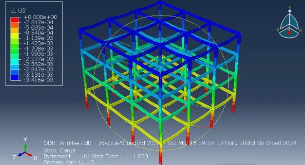
Im a Civil Engineering student and im trying to use Abaqus to do a non-linear analysis of a 20-story building with steel frame structure, and for that im running tests with simple structures to validate my modeling method.
The structure im modeling is composed of beam elements for columns and beams and truss elements for the bracing system.
Im using "join+rotation" with UR2 and either UR1 or UR3 constrained depending on the direction of the beam connectors to simulate the connection between beams and columns and using "weld" to simulate the connection between two columns. Im also using a "cartesian+rotarion" with U1,U3 and UR2 constrained connector on all the nodes of a story to simulate the floor as a rigid diaphragm.
For the step im using static,general and so far for a linear analysis my model runs without any errors and gives me the results that i want, i used other software to validate everything too
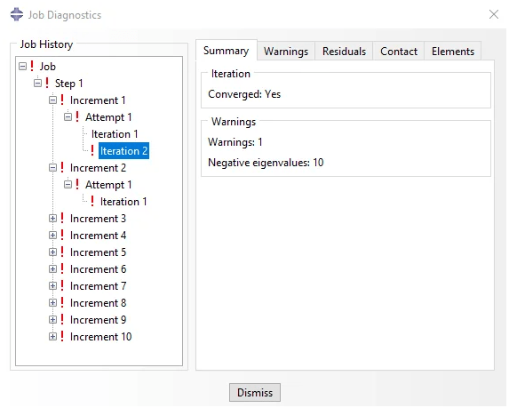
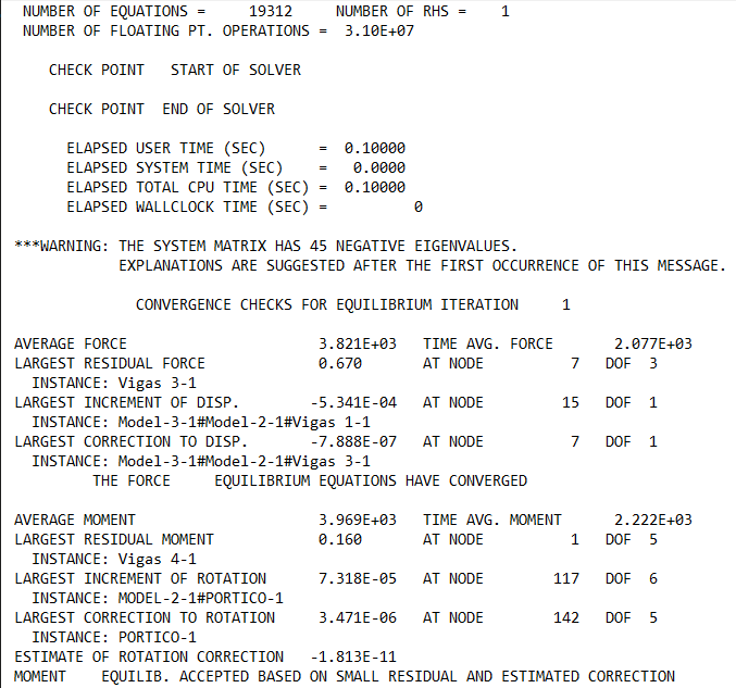
Im currently having a problem that when i turn nlgeom on and run an analysis i keep getting multiple eigenvalue errors. I dont think this is a buckling problem as the sections im using are fairly robust and none of the elements are lengthy. The loads im applying arent very big either.
Apparently lagrange multipliers can cause eigenvalue errors depending on the situations and connector elements use lagrange multipliers, altho im not sure if that is whats causing the problem for me.
Any chance someone here knows whats causing these problems? Ive been having a really hard time looking for solutions for this problem.
When i submit the job my analysis does complete and the iterations converge, but due to the eigenvalues error im not sure if my results are correct.


