Continue to Site

Eng-Tips is the largest engineering community on the Internet

Intelligent Work Forums for Engineering Professionals

  • Congratulations IDS on being selected by the Eng-Tips community for having the most helpful posts in the forums last week. Way to Go!

ABAQUS - Contact

Status
Not open for further replies.

kivl

Mechanical
Oct 4, 2019
5
Hello Everyone I have been viewing this forum for a while now and this is my first post and I hope someone could help me with this.

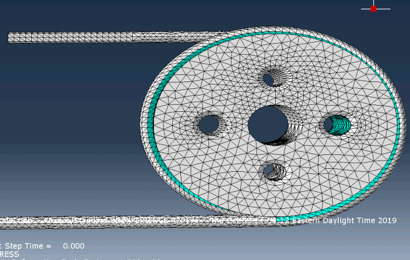
I am simulating a wrap spring clutch/brake mechanism in which a shaft is placed inside a torsion spring with an interference fit between the spring's Inner Diameter and the shaft. When the shaft tries to rotate in the direction of winding a spring wraps around the shaft making the shaft impossible to move. But on the other hand if it rotates in the opposite direction the interference is released and the shaft moves freely.

I am simulating this mechanism in Abaqus Standard where I have two different steps and two interaction property. In the first step I have included the frictionless normal behavior with the interference feature on. In the next step I am inputting the friction that will be in the system and have included a moment load.

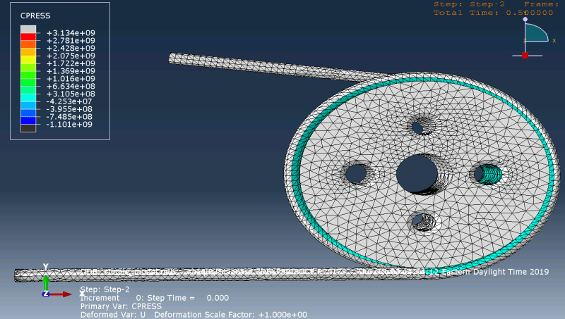
The problem that I am having is the shaft rotates but I am not able to see the contact pressure increase during rotation of the shaft can someone tell me why I am not able to visualize it?
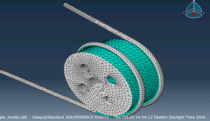
cpress_m6gdcy.png

initial_interference_model_dqfq0j.png
model_after_step_1_interference_c0uyqa.png
 
Replies continue below

Recommended for you

What do these mint green regions indicate in this case ? Is the behavior of the system the same as expected (spring winding on rotating shaft) ? Apart from CPRESS check other contact related output variables, especially CSTATUS but also COPEN. They should show you whether the contact works properly.
 
The green range states the pressure. But this color exists from the starting step of the simulation. The expected results should be at the initial step it should be blue and as we the step increases and the loads are achieved the color should turn to red. But the values in the copen doesn't make sense. The value should be with in thousands of inches but the value that I am getting is within tenths of inches. There is also this issue.
 
How is the model constrained (what are the boundary conditions) ? Is there an initial overclosure between spring and shaft ? This is typically done when modeling interference fits.
 
Yes I have given Two BC where 1st one is an Encastre at the bottom leg and the second is a rotation at the center of the shaft. I created a RP at the center of the shaft and have constrained the point to the entire shaft using the coupling constraint. I have a surface to surface interaction between the inner surface of the spring and the outer surface of the shaft where I have included allow interference. The model has an interference which is getting resolved but I am not able to visualize any contact pressure after the interference. This is the issue that I am having.
 
I don’t know much about this type of brake/clutch but in its basic form (called overrunning) aren’t both ends of the spring free ? Maybe the fixed constraint is unnecessary here. Also what do you mean when you say that coupling is connected to the entire shaft ? Is that the whole outer surface or just the surface of that large hole in the middle of the shaft. It should be the latter.
 
So the way the clutch works is that a center shaft with a diameter greater the spring inner diameter is manufactured and the spring is opened to insert this shaft in. So due to the interference there is a contact pressure from the coil of the spring to the shaft. Now when the shaft starts to rotate in the direction of winding i.e., anticlockwise in this situation the spring diameter tries to reduce but since there is a shaft in the center it doesn't allow the diameter to reduce causing a huge stress on the shaft. But on the other hand if the shaft rotates in the opposite direction it breaks free of the initial contact pressure from interference and allows free rotation. This is the working principle.

So in order to cause this mechanism to work one end of the spring should be fixed and the other end should be free. that is why i have constrained one end.

And as for the coupling can you tell me why it should it be on the inner surface of the large hole and not the entire shaft?
 
Coupling (especially kinematic type) stiffness surfaces to which it is applied (it constraints motion of their nodes to the motion of reference point). If you applied coupling to the outer surface of the shaft where it contacts with spring then it actually might be the reason of these issues with results. That’s why I suggest standard approach which is connecting coupling to the surface of the hole only. That’s where you apply rotation to the shaft after all.
 
Thank you I understand. I am changing the surface and running it at once. Thank you for your help. I will run the simulation and will let you know about results.
 
Status
Not open for further replies.

Part and Inventory Search

Sponsor