DKEngineer
Student
- Apr 3, 2023
- 20
Hi,
In Abaqus we can find the nodes belonging to the domains used to calculate the contour integral at the different contours. Abaqus documentation states:
[highlight #FCE94F]The domain associated with each contour is calculated automatically. The nodes belonging to each domain can be printed in the data file; see “Controlling the amount of analysis input file processor information written to the data file” in “Output,” Section 4.1.1. For each domain ABAQUS/Standard will create a new node set in the output database to include these nodes; you can view these node sets in ABAQUS/CAE.[/highlight]
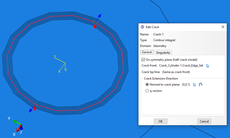
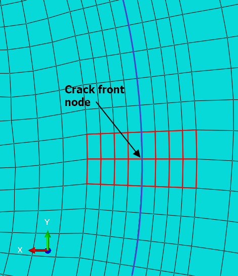
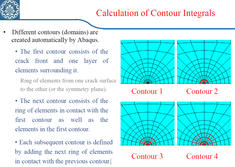
I calculate the J-integral at 4 contours (only three shown here). I am however confused with the nodes Abaqus CAE displays (figure 1-3). For the first contour, only one node is displayed, which does not correspond to the theory about the J-integral as I understand. I expected the nodes belonging to first domain to look like figuer 2, which apparently is for the second domain. I use a symmetry model with symmetry at the crack plane.
One node doesnt corerspond to any domain, since it is 1d. It needs at least one element, for the numerical integration of the J-integral.
Do I interpret the node set wrong?
Figure 1 - 1. contour domain:
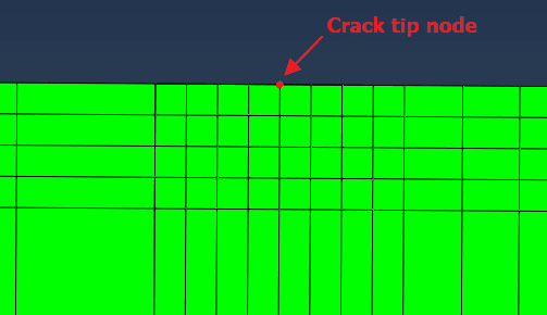
Figure 2 - 2. contour domain:
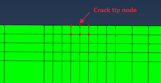
Figure 3 - 3. contour domain:
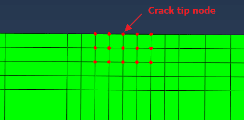
In Abaqus we can find the nodes belonging to the domains used to calculate the contour integral at the different contours. Abaqus documentation states:
[highlight #FCE94F]The domain associated with each contour is calculated automatically. The nodes belonging to each domain can be printed in the data file; see “Controlling the amount of analysis input file processor information written to the data file” in “Output,” Section 4.1.1. For each domain ABAQUS/Standard will create a new node set in the output database to include these nodes; you can view these node sets in ABAQUS/CAE.[/highlight]
I calculate the J-integral at 4 contours (only three shown here). I am however confused with the nodes Abaqus CAE displays (figure 1-3). For the first contour, only one node is displayed, which does not correspond to the theory about the J-integral as I understand. I expected the nodes belonging to first domain to look like figuer 2, which apparently is for the second domain. I use a symmetry model with symmetry at the crack plane.
One node doesnt corerspond to any domain, since it is 1d. It needs at least one element, for the numerical integration of the J-integral.
Do I interpret the node set wrong?
Figure 1 - 1. contour domain:

Figure 2 - 2. contour domain:

Figure 3 - 3. contour domain:


