Continue to Site

Eng-Tips is the largest engineering community on the Internet

Intelligent Work Forums for Engineering Professionals

  • Congratulations MintJulep on being selected by the Eng-Tips community for having the most helpful posts in the forums last week. Way to Go!

ABAQUS/explicit (dynamic,temp-disp,explicit step) EXCESSIVE DISTORTION PROBLEM HELP

Status
Not open for further replies.

mechdrive1

Mechanical
May 26, 2016
71
Hello everyone ! this is my first thread and hope that I get valuable suggestions from the experienced persons in this forum ! below is the description of my problem-
"I'm modeling a friction based welding process which involves a rigid tool being inserted into a deformable (Aluminium alloy) workpiece. I've used Johnson-cook plastic hardening with Johnson-cook rate dependency (initially it was the plasticity) to see if has some +ve effects on my model, but it didnt. I have used C3D8RT elements for both tool and workpiece.I've used a fine mesh for the interaction region (for tool and workpiece) and coarse mesh otherwise. The tool has an angular velocity of 400 rads/sec with a feed rate of 0.5 mm/sec whereas the bottom surfaces of workpiece are encastre'd. I've given the movement to the tool by using 'tabular' amplitude increasing in paced manner. In the step, i've specified non-linear geometry with mass scaling for the concerned interaction (tool & workpiece) region (factor-10^8) at the beginning of step (it does increase the stable time increment). I've used ALE adaptive meshing with a frequency of 1 and remshing sweeps as 50-75, I've chosen frequency of 1 so that I can specify ALE mesh constraint for the workpiece (only the region where tool is inserted). I even tried element deletion, although I didnt specify any damage criteria in material module (dont know if it's necessary). the total time period of my analysis is 4 seconds and a pressure of 80Mpa is applied on the tool. I would like to clarify that I've checked the units of the material properties 'n' number of times and there's no worry over there. Whenever i run the analysis, the model reaches a time period of only 0.86 seconds with stable time increment of 1.0E-6. the mesh gets excessively distorted and analysis is aborted.
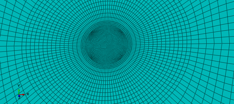
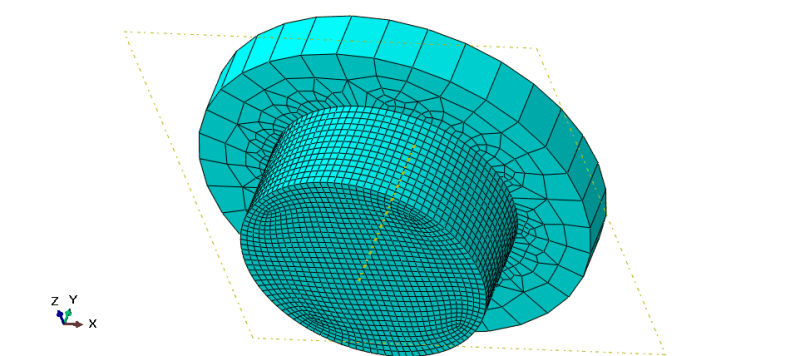
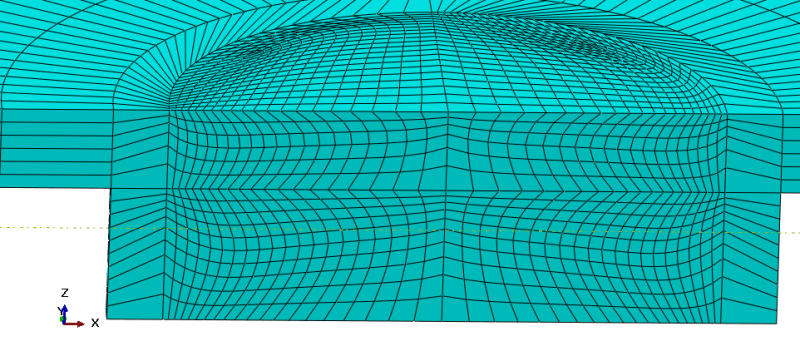
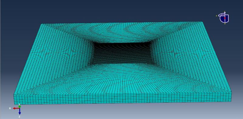
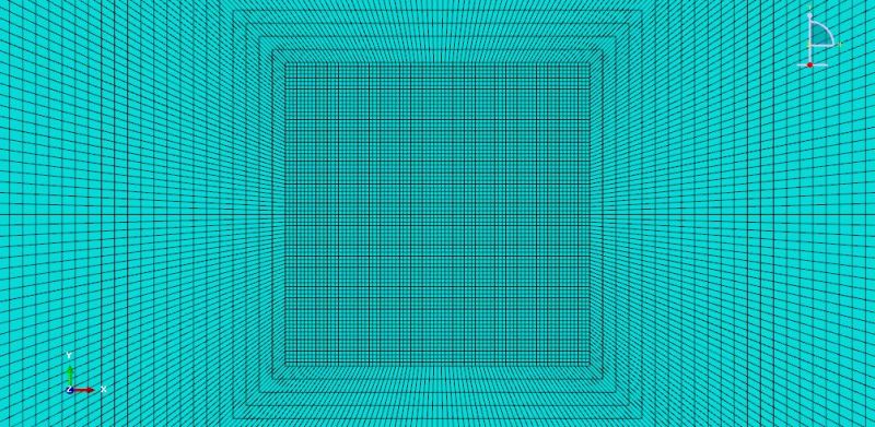
I am attaching images of the meshed assembly and also models.
---->
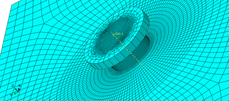
A4_zjzdmq.png

---->
WP3_ndyzbg.png

----->
T1_cbgpls.png

----->
Please anyone who has knowledge about this issue or have faced same problem, give your suggestion/advise that can be used to resolve this issue. I've tried looking in literature of similar processes for a solution, but couldnt find any !
Thanks in advance !!
 
Replies continue below

Recommended for you

Hi mechdrive1
First of all, see below link:
Link
By the way if you ask my opinion and Based on my experience (I did not work with mass scaling and i can't say anything about that) answer below Questions:
1) Did you use Johnson-cook Damage ?
2) Did you use Damage evolution ?
3) What is your Element library ?
4) Can you take a Picture from model in 0.86 seconds, without Tool ?
5) Can you Write your Field Output Variables (In Step Module) ?
With Best regards.
yassou.
 
Firstly I would like to correct myself, the analysis stopped at 0.75 seconds and not at 0.86 seconds as I mentioned in the post (this value is from other model) and apologise for this. The answer to your questions are:

1. I haven't specified Johnson-Cook damage as I thought material in the model undergoes plastic deformation (although quite high) and isn't removed from the model unlike machining processes. Although, I've used Johnson-cook module in the 'plastic' definition of material property module.
2. I didn't use damage evolution either and can you point out where I can find it ?
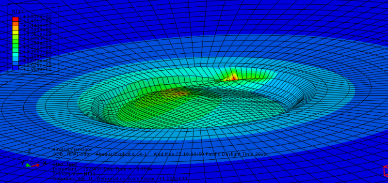
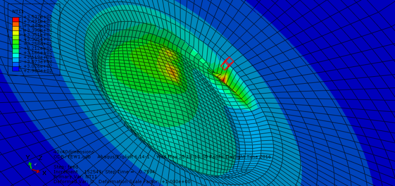
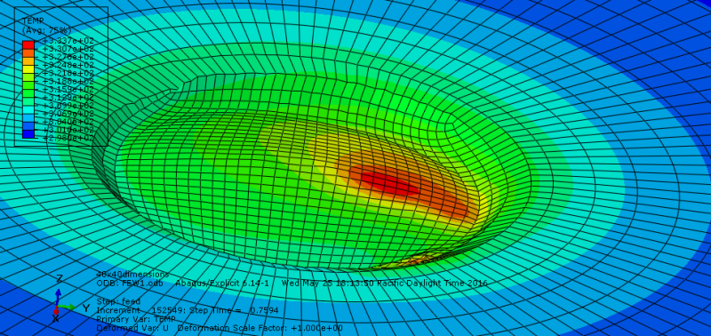
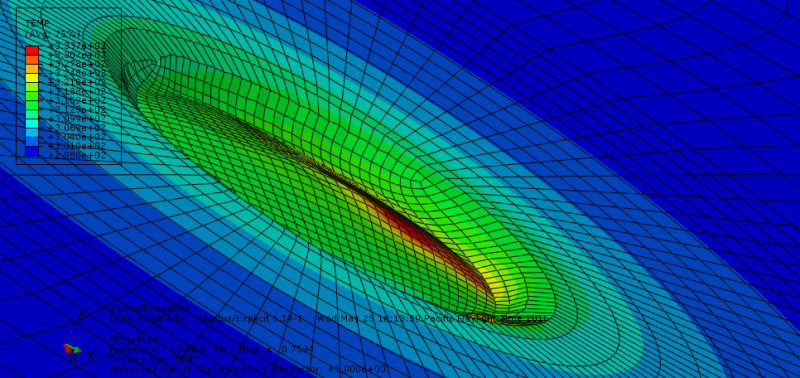
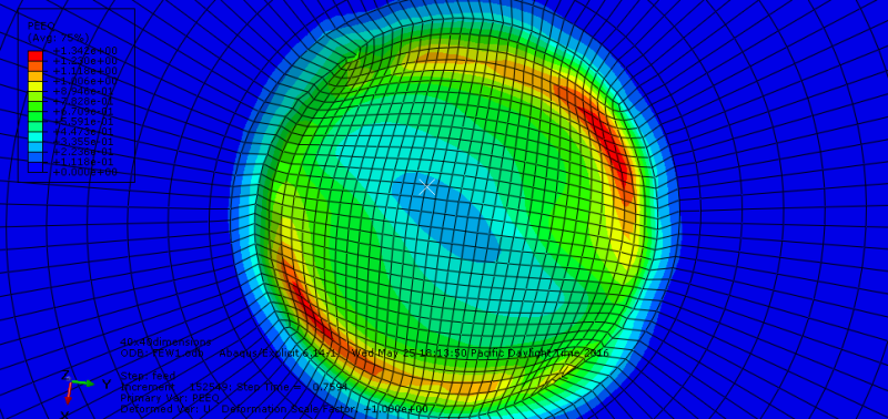
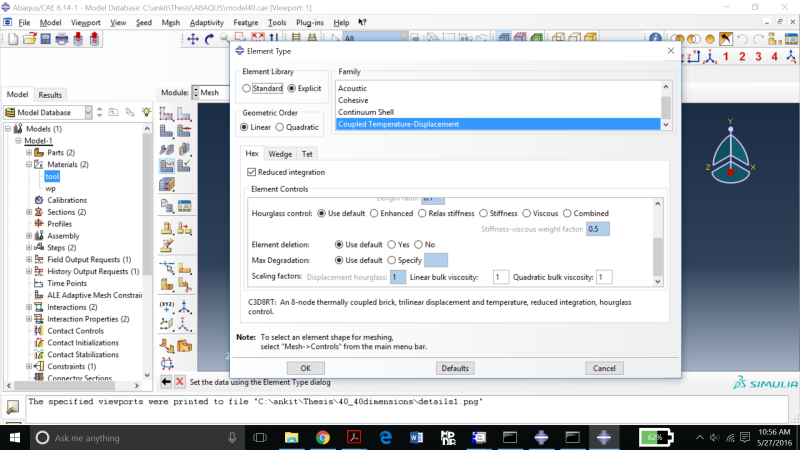
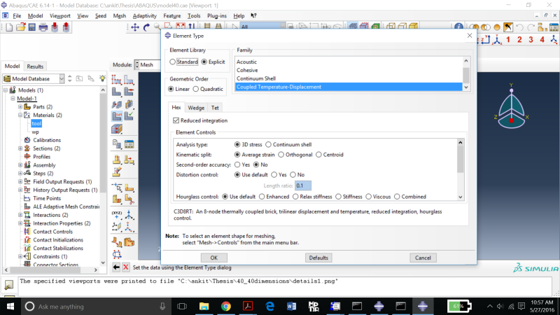
3. By element library, do you mean the type of elements I've utilized in meshing of the parts? If so, then I've used Hexahedral elements (C3D8RT) with default settings and used a structured mesh in the mesh controls. I'll post a pic of the specifications I've used. Below are the pics of element temperature,temperature (avg) and PEEQ results at step time of 0.7594 seconds.
--->
eletemp3_d7nnkl.png

--->
eletemp2_wtlfx1.png

--->
temp1_lhiqdt.png

--->
temp2_hvok08.png

--->
PEEQ1_ftpkau.png


pics of specifications of element:
-->
2016-05-27_1_z4jlzr.png

-->
2016-05-27_2_uhzsov.png


I'm sorry but I didn't get what you mean by field output variables ? ( which variables should I provide info about ?)

Also, I would like to add that I have given interaction between the bottom surface of the tool and top surface of the workpiece and also between the side surfaces of the tool and the nodal region of the workpiece where interaction takes place. I've specified a value of 0.4 and 0.2 for co-eff. of friction for the two interactions respectively. Both of them are surface-to-surface interaction (explicit).

I've gone through the link and would like to mention that my units are consistent (mm-MPa-Tonne-K) and are from a reliable established source. In the other models which I've developed, I used low mass scaling factors but it didnt resolve the issue.

Thanks
 
Then you don't want to have "Element Deletion", Beacuse you say:
[u said:
mechdrive1[/u]] I even tried element deletion,...
OK, your model is some sort of Friction Stir process.
Try Below steps:
1) In Kinematic split, use Orthogonal.
2) In Distortion control, yes (0.1).
Also see below Link (specially Time of simulation):
Link
With Best regards.
yassou
 
Dear Yassou,

I tried the element deletion and distortion control in my earlier models, but it didn't help either and yes my process is quite similar to FSW process and the time period is a second less than FSW process as shown in the link. I will try to change the kinematic split and run the analysis. Can you please tell me if ALE mesh constraint will help me in running the analysis without distortion.
 
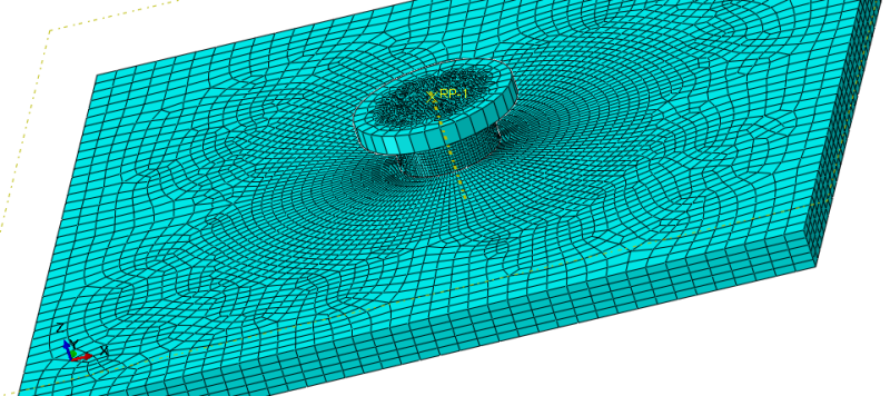
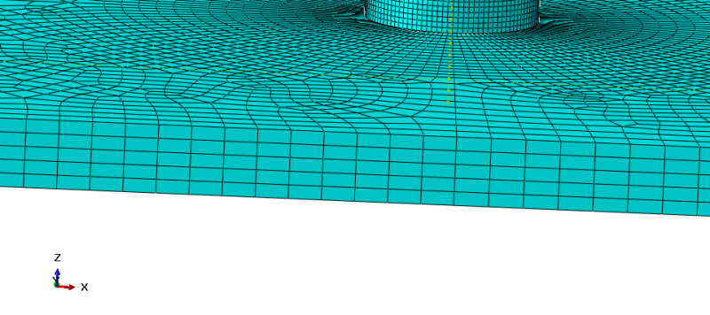
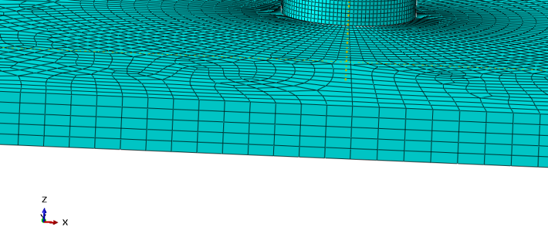
Looks like you have some hourglassing going on in there. Can you show a cross section view of the aluminum body? How many elements through the thickness?

I have never used adaptive meshing, but you may want to try a finer initial mesh in the problem area?
 
Dear Cooken,

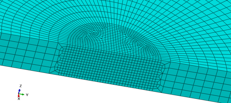
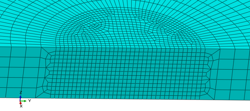
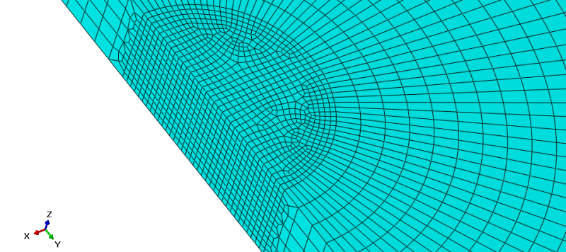
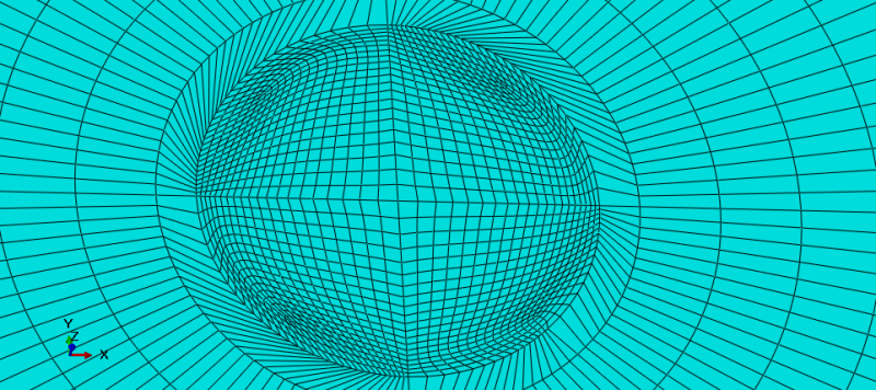
I have used default Hourglass control as can be seen in the above pic, although I tried using 'enhanced' but there wasn't much difference in the analysis. Below are the pics of the meshed assembly, in the pic you can see that I've used sweep mesh controls (just trying out different things to see which one works out). I have used finer mesh in the region where interaction between tool and w/p takes place and have gradually increased the mesh size from there towards outside.

x-s2_o89si5.png

x-s3_wjgzbi.png

x-s4_q1k1cz.png
 
Try a section cut through the middle so you can see what it looks like through thickness at the refined area. Many of your elements probably have poor aspect ratios, and also if the 5 elements through thickness is constant all the way through, this may not be nearly enough where the large deformation is happening. Also check your energy balance, I would guess your artificial strain energy is quite high.
 
Indeed, cooken offer can be correct.
By the way, Follow below steps:
1) Partition in XZ and YZ (Divide model in 4 equal quarter) and also after that use circular partition (Tool position should be in center).
2) For ALE try this: Frequency:10, Remeshing sweeps peer increment:1
3) See if you can use Structural meshing, use it, No, the Use medial axis method (Because of partitioning method).
4) Use Proper Seed Edge (It's Better to use Same Size Elements, not bias)
5) In Kinematic split, use Orthogonal.
6) In Distortion control, yes (0.1).
With Best regards.
yassou
 
Dear Cooken,

As you can see in the pic, the density of mesh isn't 5 in the region where tool and wp interaction will take place, I've used quite a refined mesh in my earlier models but the result has been the same (distortion after some time). Can you please tell me more the checking of energy balance ? I'm not sure how it should be done. I'm attaching pics of the cut view of the concerned region.
cutview1_meknvn.png

cutview2_hyoivs.png

cutview3_fxyfgk.png


Thanks.
 
Dear Yassou,
My model is already divided into four regions as I wanted to make the tool touch at the centre of the woorkpiece.
I've tried the ALE frequency of not only 10 and remeshing sweeps as 1, but also different settings.
I've used both structured meshing and swept mesh in my models, but the results are same.
I didn't use biased meshing and seeded the edges with the required element size.
Regarding distortion control, ABAQUS shows an error saying ALE mesh control and distortion control cannot be used simultaneously (perhaps it was for ALE adaptive mesh constraint), but the point is distortion control hasn't helped either.

I was trying to give ALE adaptive mesh constraint, but an error crops up saying "ale adaptive mesh constraint cannot be applied on non-adaptive nodes". I specified adaptive mesh constraint only for the region (circular hole) where tool will be inserted.

Thanks.
 
Hi,

The elements in the region where you transition from 5 to 13 elements through the thickness of your part look poorly shaped. This is also the region where you see your highly distorted elements. I would take another look at the mesh - use biased seeds so that your element shape doesn't change abruptly over a single element length.

Good Luck,
Dave
 
Dear Dave442,

Hello.

you're correct that I observe excessive distortion in the transition region. I'm not sure how I can give correct biased meshing, there are two types in it- single and double. Also, I'm not sure what does the direction of arrow means in it. Can you please help me out with it.

I am attaching my model's .inp file. I would appreciate it if you can go through it and give me feedback and/or make corrections in it.
Thanks.
 
 http://files.engineering.com/getfile.aspx?folder=f8063c75-3c43-4ec8-84b6-741e1db93096&file=FW1.inp
Hi,

Read 'Section 17: The Mesh Module' in the Abaqus/CAE User's Guide. Specifically, 'Section 17.4.3: Controlling the Seed Density':

Specify a nonuniform distribution of elements along an edge.
The element density can increase from one end of the edge to the other (single bias), or the element density can vary from the center of the edge to each end (double bias). For a nonuniform distribution you can specify either of the following:
[ul]
[li]The number of elements desired along an edge and a bias ratio. The bias ratio is the ratio of the largest element to the smallest element.[/li]
[li]The size of the smallest element and the size of the largest element.[/li]
[/ul]

Good Luck,
Dave


Dear Dave,

As you suggested I had gone through the seeding distribution in the documentation and subsequently gave biased mesh in the region where interaction takes place. I gave single bias with minimum size of 0.05 and maximum size of 0.25 for the workpiece and ran the analysis. Unfortunately, it doesn't seem to work either and I'm back at square one. Also, now I'm thinking of converting the model into an CEL model and try it. I'm attaching images of the meshed region.

Thanks.
bm1_nskqcj.png

bm3_ndjgdq.png
 
Your mesh is even worse now.

Look at the change in element size over the first three elements as you move from left to right on your second image. Also, lots of badly shaped elements in the contact/transition regions due to whatever way you have assigned the seeding. I suggested using biased seeding to remove the abrupt change in element size as you moved radially outward from the contact region. Not to re-mesh your contact region - as you have done. You want your element shape to be as close to a cube as possible. And the element size should increase gradually as you move from the central contact region through the transition region then more abruptly as you approach your part boundaries.

Good Luck,
Dave

 
Hi Again
OK, You need something like this:
S1_r76f2l.jpg

And:
S2_aqktnw.jpg

Am i Right?
I upload the .sat file in metric unit (0.4 in 0.4 in 0.02 meter).
With Best Regards.
yassou.
 
BTW, IceBreakerSours you are Right, But unfortunately it gain from experience....
NO PAIN, NO GAIN.
With Best Regards.
yassou.
 
Dear all,

@Dave422- I can understand my mesh isn't what you're suggesting, I'll make the corrections but as I'm relatively new (first time using ABAQUS) you can understand that some definitions in the documentation can be misinterpreted.

@IceBreakerSours-Regarding CEL, yes it's computationally expensive and is my last resort if the ALE formulation doesn't work.

@Yassou- Thank you for helping with the meshing, appreciate it a lot. However, when I open your .sat file by using import part option, the mesh isn't being generated, only the part is imported without the mesh. Should I import it in other manner ?

Thanks to all.
 
Status
Not open for further replies.

Part and Inventory Search

Sponsor