Continue to Site

Eng-Tips is the largest engineering community on the Internet

Intelligent Work Forums for Engineering Professionals

  • Congratulations MintJulep on being selected by the Eng-Tips community for having the most helpful posts in the forums last week. Way to Go!

ABAQUS/explicit (dynamic,temp-disp,explicit step) EXCESSIVE DISTORTION PROBLEM HELP

Status
Not open for further replies.

mechdrive1

Mechanical
May 26, 2016
71
Hello everyone ! this is my first thread and hope that I get valuable suggestions from the experienced persons in this forum ! below is the description of my problem-
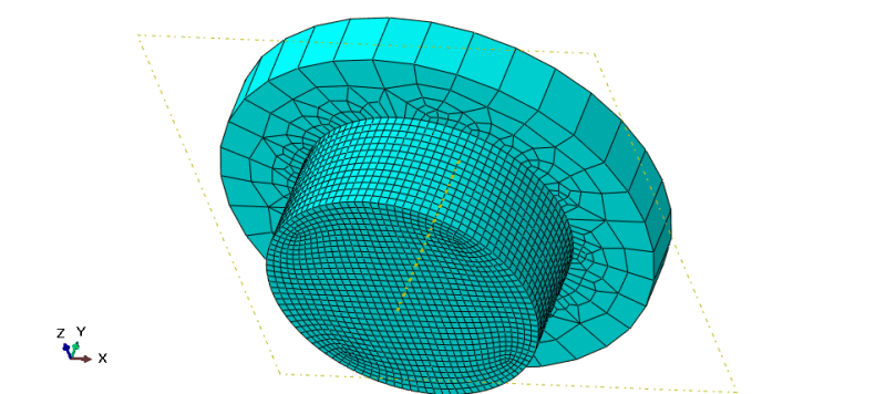
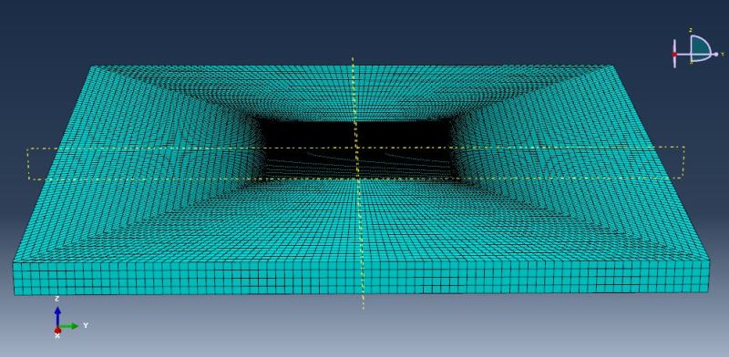
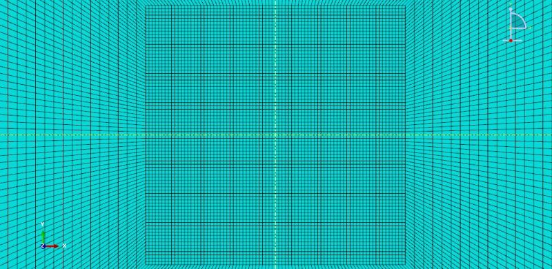
"I'm modeling a friction based welding process which involves a rigid tool being inserted into a deformable (Aluminium alloy) workpiece. I've used Johnson-cook plastic hardening with Johnson-cook rate dependency (initially it was the plasticity) to see if has some +ve effects on my model, but it didnt. I have used C3D8RT elements for both tool and workpiece.I've used a fine mesh for the interaction region (for tool and workpiece) and coarse mesh otherwise. The tool has an angular velocity of 400 rads/sec with a feed rate of 0.5 mm/sec whereas the bottom surfaces of workpiece are encastre'd. I've given the movement to the tool by using 'tabular' amplitude increasing in paced manner. In the step, i've specified non-linear geometry with mass scaling for the concerned interaction (tool & workpiece) region (factor-10^8) at the beginning of step (it does increase the stable time increment). I've used ALE adaptive meshing with a frequency of 1 and remshing sweeps as 50-75, I've chosen frequency of 1 so that I can specify ALE mesh constraint for the workpiece (only the region where tool is inserted). I even tried element deletion, although I didnt specify any damage criteria in material module (dont know if it's necessary). the total time period of my analysis is 4 seconds and a pressure of 80Mpa is applied on the tool. I would like to clarify that I've checked the units of the material properties 'n' number of times and there's no worry over there. Whenever i run the analysis, the model reaches a time period of only 0.86 seconds with stable time increment of 1.0E-6. the mesh gets excessively distorted and analysis is aborted.
I am attaching images of the meshed assembly and also models.
---->
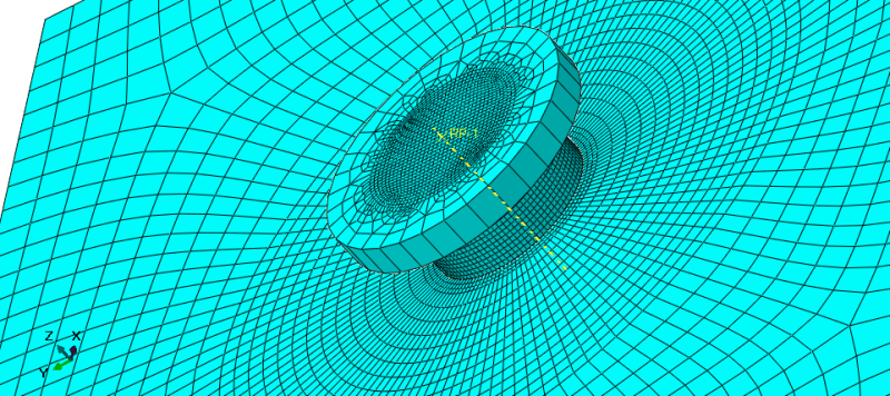
A4_zjzdmq.png

---->
WP3_ndyzbg.png

----->
T1_cbgpls.png

----->
Please anyone who has knowledge about this issue or have faced same problem, give your suggestion/advise that can be used to resolve this issue. I've tried looking in literature of similar processes for a solution, but couldnt find any !
Thanks in advance !!
 
Replies continue below

Recommended for you

No, It's fine, It depends on you how to mesh it...
For example, follow below Steps:
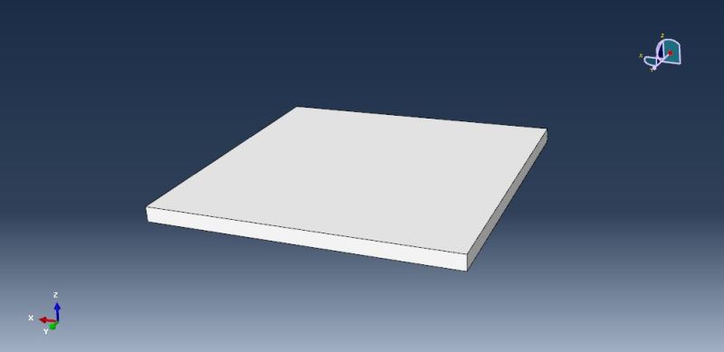
1) This is Base Model:
1_ewwpyb.jpg

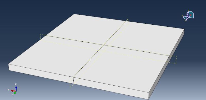
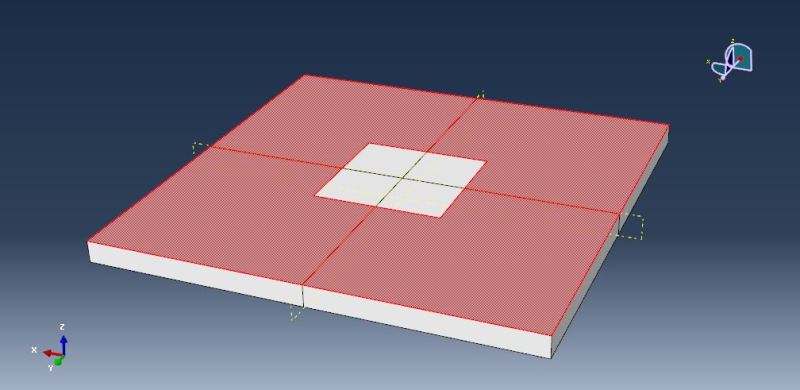
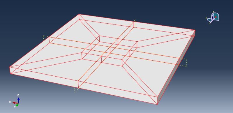
2) Partition it Like This (4 equal square):
2_l5y8pg.jpg

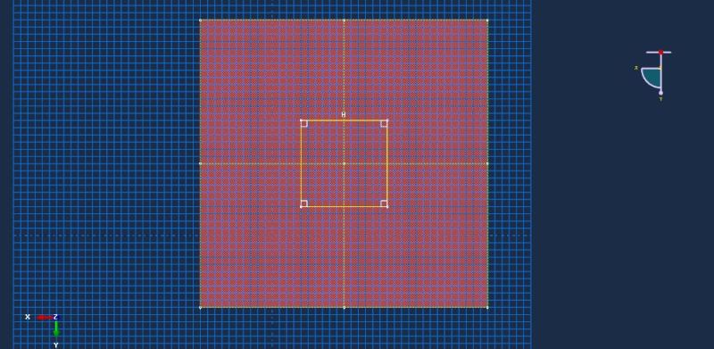
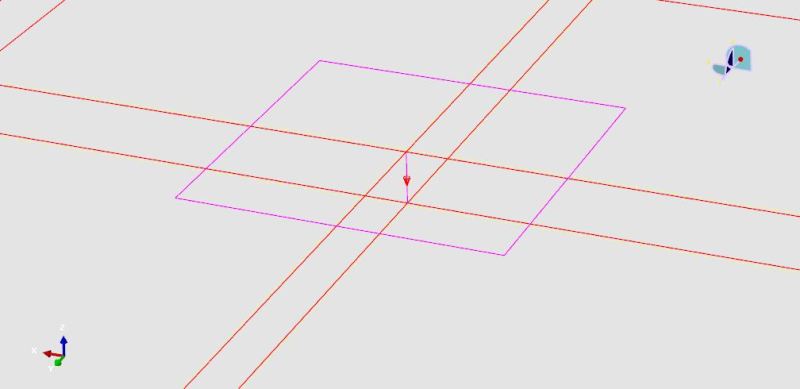
3) Use Partition face sketch tool like this :
3_saxkon.jpg

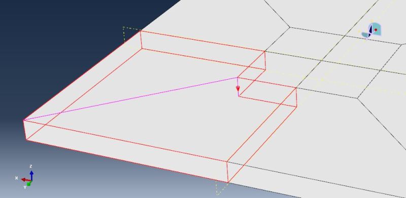
4) Use Partition Cell: Extrude/Sweep Edges tool Like this:
4_wwztya.jpg

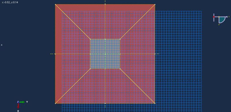
5) Again use Partition face sketch tool like this :
5_c9oq3k.jpg

6_wmkhkk.jpg

6) Again use Partition Cell: Extrude/Sweep Edges tool Like this:
7_coupbo.jpg

7) Do Step 6 for other sections, End Geometry is this:
8_wdykdz.jpg

Now is Meshing Time:
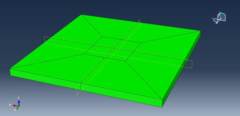
8) Go to Mesh module, As you can see All sections is Structured:
9_krgmdh.jpg

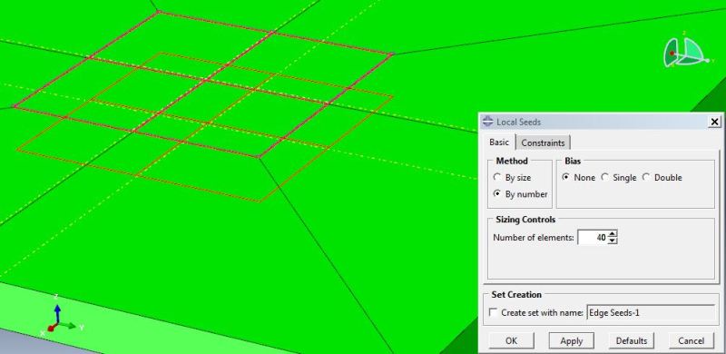
9) Use Seed Edges tool for this Edges:
10_waxiuj.jpg

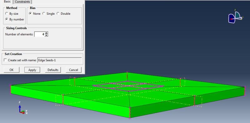
10) Again use Seed Edges tool for this Edges:
11_gdhira.jpg

11) Your Final Model is this:
12_wqobwn.jpg

13_emdehk.jpg

You can modify any step of this instruction (depends on you or your Project).
With Best Regards.
yassou.
 
Dear Yassou,

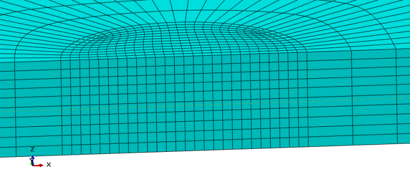
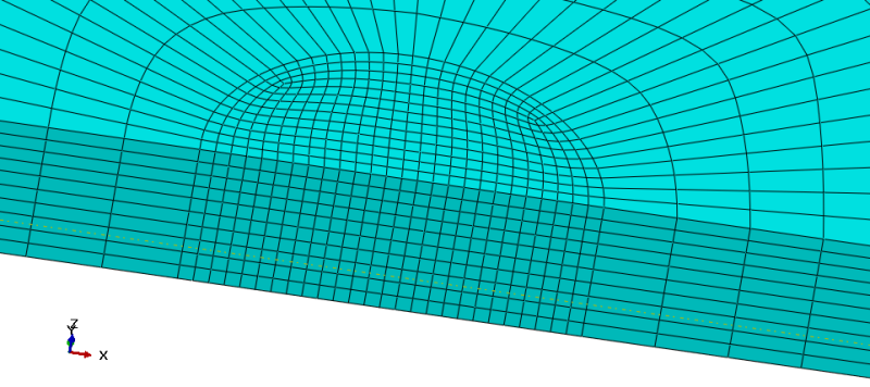
Thank you for giving time to my problem and helping in resolving it. I followed steps as suggested by you, however, I had to make some modifications. I'm attaching pics of the meshed region.

c2_vxsnt8.png

c3_fq8xjb.png


I'm running the analysis and waiting for results. I haven't opted for a fine mesh as you had to reduce computation time.
 
MechDrive,

You are just repeating your mistake, this mesh looks even worse than your original one.

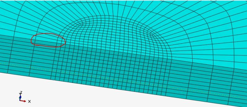
It looks like you have just made the fine mesh region extend to exactly the diameter of the rigid tool, or at most a couple of elements beyond, then you go directly to much bigger size and poorly shaped elements (see circled elem below). You need to have smaller, better shaped elements in areas of high strain gradient, which will be from the edge of the tool to probably 1.5 to 2 times the tool diameter. Look at your contour plots abaove - you need to have your fine mesh extend out to where it turns light blue, and transition to bigger elements from there to the dark blue region.

BadElem_uugvot.jpg
 
hello
i am doing analysis of inertia friction welding process on ansys 15.0.
while doing so i am getting error about following-
1-element type 1 is not same as solid226.
2-extensive distortion.
3-problem in defining mesh for the solid element and contact region.
plz help me if u can.
 
Hi nimesh32
I think you asked your question in a wrong forum (this is Abaqus software forum), For more information see below Links:
Link
Link
With Best Regards.
yassou.
 
Dear All,

I apologise for the late reply. I have been trying different settings in the mesh element type and the mesh itself. To get results quicker, I increased the feed rate from 0.5 to 25 mm/sec and was able to get till 60-70% of the first layer. What I've observed is that the elements are getting compressed, and still not able to resolve the distortion problem.
I have given Eulerian boundaries on two side surfaces of the workpiece (inflow and outflow).
In the ALE mesh controls, I've given 0.5 value each to volumetric and equipotential smoothing method.
In the hourglass control section in element type, I have used 'combined' method with 0.7 ratio. (element is same as previously mentioned i.e. C3D8RT).
I'm attaching a video of my result. I would appreciate any further suggestion/advice to improve my model.
 
 http://files.engineering.com/getfile.aspx?folder=55b34b51-cbc6-44b4-ae41-183e63fa2c86&file=1.mov
Hi mechdrive1
Can you Write your Warning and Status file info's (Select the Text, Use Cnt+C to copy, In Topic,"Reply To This Thread" Use Quotes tool to add it in here with Cnt+V) ?
With Best Regards.
yassou.
 
Hi mechdrive1
Abaqus said:
WARNING: There are 13479 warning messages in the data (.dat) file. Please
check the data file for possible errors in the input file.
Did you read this ?!
First of all you should solve this ...
One By One.
For Example:
Abaqus said:
Boundary conditions are specified on inactive dof of 1496 nodes. The nodes have been identified in node set WarnNodeLoadBCInactiveDof.

Boundary conditions are specified on inactive dof of 2992 nodes. The nodes have been identified in node set WarnNodeLoadBCInactiveDof.
This Means your Boundary Conditions are not right.....
If I were you, i forget what have been done until NOW and Create a new model with respect to the previous Simulations, "Warning" and "Status File".
I think in That Time your problem will be solved.
With Best Regards.
yassou.
 
hello everyone !

I created new model altogether, but still got similar warnings and the excessive distortion error. Now, I'm modeling with CEL approach and it's quite computationally expensive even for a coarse mesh. I had one question regarding the CEL method, how do we give thermal interactions such as surface radiation and convection to the eulerian part (mesh). Will it work if I specify thermal interactions in a way similar to specifying to lagrangian part ?

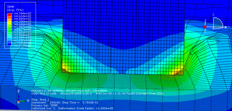
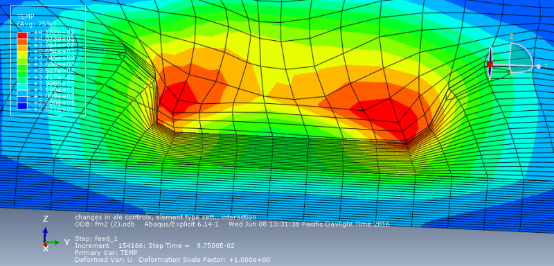
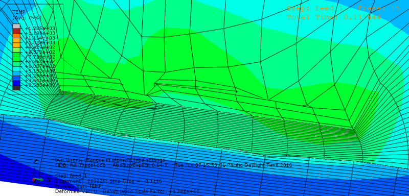
I'm uploading pics of my lagrangian model results which I got after changing ALE settings and element controls.
3_exepct.png

4_uhko9z.png

6_m6emw2.png
 
So you achieved a result...great. Is it meaningful? Looking at those plots I would say no. Your mesh is still bad, and can you not see the large amount of penetration? Why are the elements on the rigid tool smaller than the deformable ones??
 
Dear Cooken,

I never mentioned that these are the final results, I mentioned them as the results of a particular job in which the tool has gone the farthest so far. I too have noticed that the tool is penetrating the workpiece elements and therefore tried different shape of the tool. But the analysis couldn't run for much time due to mesh distortion and as such I've shifted to CEL approach, although I'm finding it to be computationally very expensive even for a coarse meshed model.

Thanks.
 
Status
Not open for further replies.

Part and Inventory Search

Sponsor