Continue to Site

Eng-Tips is the largest engineering community on the Internet

Intelligent Work Forums for Engineering Professionals

  • Congratulations KootK on being selected by the Eng-Tips community for having the most helpful posts in the forums last week. Way to Go!

ABAQUS-Local Co-ordinate System in Kinematic Coupling

Status
Not open for further replies.

Entherm

Civil/Environmental
Sep 23, 2020
34
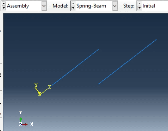
In the below figure, the local axis is defined such that the X is parallel to the longitudinal axis of the left beam. In ABAQUS, if I define kinematic coupling say constrain U1 with the master for left beam and slave for right beam, will U1 still be the axial/longitudinal axes for the left beam as the beam deforms?
Issue8_r8hayu.png
 
Replies continue below

Recommended for you

In analyses with Nlgeom on, coordinate system used for the definition of kinematic coupling rotates with reference node. For more details check the documentation chapter "Kinematic coupling constraints" (last paragraph).
 
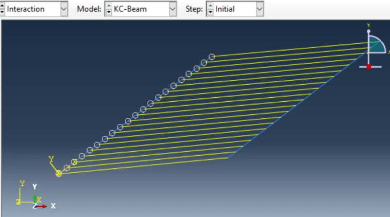
Thank you FEA way. Can you please help me understand what happens in this case where there are kinematic couplings defined for every node in the beam. Do we define a coordinate system for each node? I have been stuck in this for a long time.

Issue9_zkqksn.png
 
You can use a single CSYS for all couplings unless you need different axis orientations for them. However, I’m not sure of it’s a good idea to apply coupling constraints to all nodes of the beam. This way you will make it stiff. What is the purpose of the simulation ? There might be a better way to realize this connection.
 
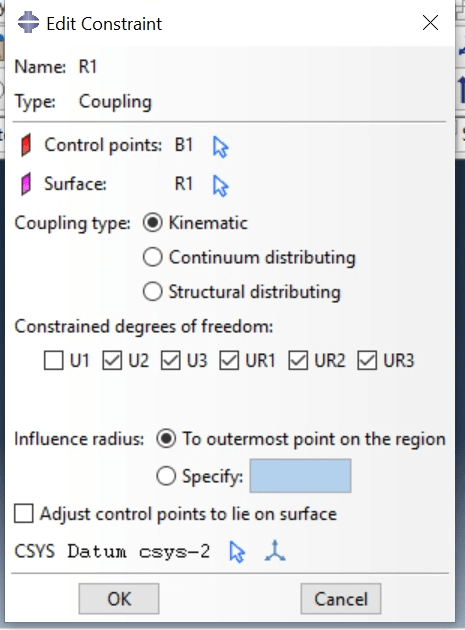
@FEA way, I am in fact, trying to make the left beam stiff. I have the following type of kinematic coupling defined for each node in the beam. B1 node is on the left beam and R1 on the right beam.
The beam on the left has less buckling capacity but we have to apply axial load beyond its buckling load so to make it stiff we couple it with the right beam but do not constrain U1 because the right beam should not interfere with the axial displacement of the left beam.
It seems to be working fine for linear material but does not work beyond yield point (NLGeom on for both cases)
Issue10_kzcqvr.png
 
If the results you get are different than expected then you may have to use different type of constraint (their descriptions, including behavior in nonlinear analyses, can be found in the documentation) or maybe even change the whole approach to this problem.
 
Status
Not open for further replies.

Part and Inventory Search

Sponsor