Hello,
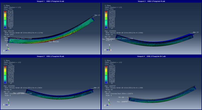
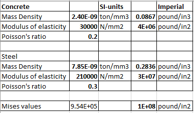
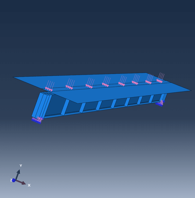
As practice, I have simplified a steel-concrete composite bridge to one 3D beam model with effective width of concrete. The beam length is 21.3m and concrete effective width is 2.7m. I used tie constraints to simulate the interaction between the concrete deck. I am following the base units of ton, mm and N for abaqus and currently modelling using elastic materials only. However I am not comfortable with he final values I am gettign for the von mises stress. In addtion to the selfweight, I have applied a UDL load of 1kn along the area of the flange girder which is 300mm wide. I am getting values of 1.117e6N/mm2 for the von mises stresses. can some one help me? Am I interpreting the units von mises values wrongly? I think the value I am getting is too large because when i change the steel material to trilinear material with yield stress of 355MPa and ultimate strain 0.18,, I get the error of strain increments are too large. I have triple checked the input units multiple times. The other input values are mass density for steel is 7.85e-9, for concrete 2.4e-9, acceleration -9810, E (Youngs modulus) concrete = 30000 and v =0.2, for steel E = 210,0000 and v =0.3.
The girder is UB beam 1016x305x272 with concrete deck thickness of 250mm. I have been trying to compare the values when i add stiffners to the web.


