owais ahmed
Student
- Nov 10, 2021
- 10
Hallo everybody,
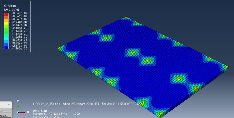
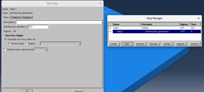
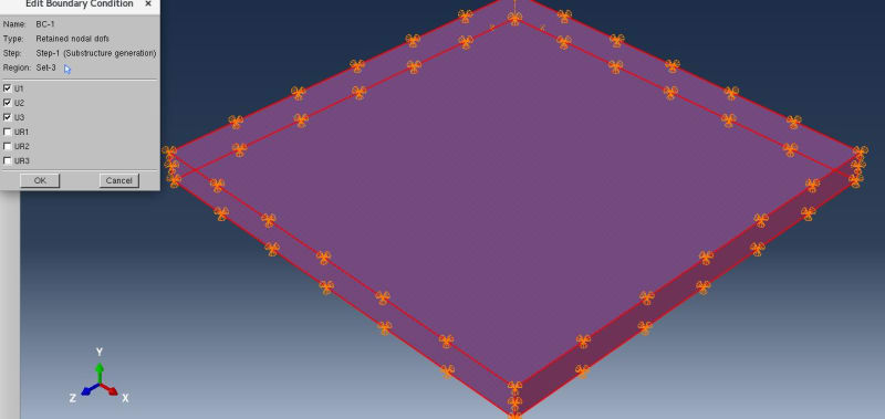
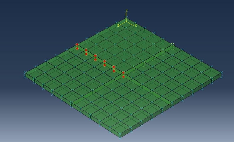
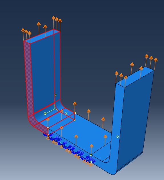
I have been working on substructure simulation.Firstly i run my simulation just like a normal case and obtained the misses stress results. Secondly i try to validate the simulation by using substructure modelling for that i simulate a subtructure with nodal degree of freedom and then import .sim 4 files to main model one by one after assembling i apply tie contacts in between the substructures.by node to surface contact.after tie contact load is define and simulations is run.But in substructure i am getting the misses stress values 10 times higher than the normal case? Why is this so? i check it by dividing my structures into six parts and ten parts and after apply tie conctact and simulations running.i am getting the results which is misses stresses(pattern is also not the same) 10 times higher than the normal case. Also other pattern of the stress distributions is also not the same which i am getting without substructure modelling? Thank you for any of your responses
I have been working on substructure simulation.Firstly i run my simulation just like a normal case and obtained the misses stress results. Secondly i try to validate the simulation by using substructure modelling for that i simulate a subtructure with nodal degree of freedom and then import .sim 4 files to main model one by one after assembling i apply tie contacts in between the substructures.by node to surface contact.after tie contact load is define and simulations is run.But in substructure i am getting the misses stress values 10 times higher than the normal case? Why is this so? i check it by dividing my structures into six parts and ten parts and after apply tie conctact and simulations running.i am getting the results which is misses stresses(pattern is also not the same) 10 times higher than the normal case. Also other pattern of the stress distributions is also not the same which i am getting without substructure modelling? Thank you for any of your responses