Continue to Site

Eng-Tips is the largest engineering community on the Internet

Intelligent Work Forums for Engineering Professionals

  • Congratulations pierreick on being selected by the Eng-Tips community for having the most helpful posts in the forums last week. Way to Go!

Abaqus radial expansion and rotation

S2196L

Mechanical
Feb 13, 2025
4
Hello Everyone,

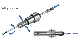
I need a help regarding simulation of tube rolling process which constists of 3 rollers that are radially expanding and rotating.
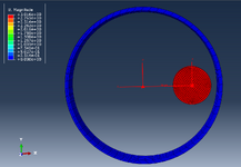
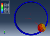
First thing first I'm trying to conduct simulation of just one roller kinematics so that the roller expands and rotates.
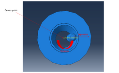
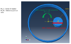
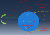
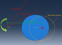
I need to have roller expansion and rotation (around center of the tube - center point), but when using coupling constraint Roller_reference (RP) is moved with the roller from the center point and the rotation is then from this reference point that has been moved with the roller from the center of the tube
When I try using 2 reference points sometimes it gives certain errors due to this.
Thank you for your help.
 

Attachments

  • Roller radial expansion.png
    Roller radial expansion.png
    114.6 KB · Views: 3
Replies continue below

Recommended for you

You could use connectors for that. Something similar to this thread: https://www.eng-tips.com/threads/axial-hinge-connectors-displacement-issues.520670/
Hello,

Thank you this helps.

But with the connector I'm not able to get rotation of the roller around center of the tube.

The displacement is fine and the rotation of the roller is around his own axis and not center axis, do you know what is the problem?
 
Which type of connector are you using ? How did you define its orientation (local coordinate system) ? A screenshot showing your setup with the connector may help.
 
Hello,

Find the screenshots in the attachment of the simplified model and also of the rolling process.
Additionally explanation of the tube roll expansion process can be seen on this YT video:

I have manage to get both rotation (STEP 2) and radial expansion (STEP 1) in this order using hinge connector
If I have first radial expansion and then rotation around central axis RP_C the simulation is aborted or the result is not okay, I belive reason for this is the cartesian coordinate system, not sure if cylindrical coordinate system might help?

On the picture "Roller after 1_STEP rotation and 2_STEP radial expansion" you can see the roller doing one full circle of rotation after which he is radially expanded in X direction
On the picture "Roller after 1_STEP rotation, 2_STEP radial expansion and 3_STEP rotation" you can see what happens once you apply rotation of roller after radial expansion (movement in X direction)

For the full simulation I will have 3 roller, the simulation will consist of few steps in which I will gradually increase the radial movement of the roller with the constant rotation of the roller around center axis.

The biggest problem is how to prescribed the radial movement out from the central axis so that the roller during rotation has same radial distance from the center axis as for now I give certain X direction displacement and during rotation it causes problems as seen on the pictures (just my opinion)

Unfortunately I couldn't attach the videos.

Best regards
 

Attachments

  • Rolling Process.png
    Rolling Process.png
    137.3 KB · Views: 3
  • FEA model.png
    FEA model.png
    147.8 KB · Views: 2
  • Roller after 1_STEP rotation and 2_STEP radial expansion.png
    Roller after 1_STEP rotation and 2_STEP radial expansion.png
    115.9 KB · Views: 2
  • Roller after 1_STEP rotation, 2_STEP radial expansion and 3_STEP rotation.png
    Roller after 1_STEP rotation, 2_STEP radial expansion and 3_STEP rotation.png
    124.9 KB · Views: 1
Try with the Cartesian + Align connector combination as I suggested in the thread referenced above.
 
It doesn't work fine with this combination Cartesian + Align it is much better with Hinge
Please find attached 2 schemes, one scheme shows the rotation of the roller and second shows distance problem.

The problem is when I apply displacement in X direction for 2 mm the roller will move 2 mm, but during rotation I think Abaqus is trying to keep this displacement and it goes crazy.
How can I set that during rotation the RP_R ref point is always at the same distance from center RP_C?
This is the only problem if somehow I can define that the during rotation Abaqus keeps the distance of these 2 ref points constant it would be great.

On the picture I want to have this length A (distance between the RP_C and RP_R) constant during rotation which I belive will fix all problems.

The cylindrical system somehow is not working properly for now
 

Attachments

  • Roller rotation scheme.png
    Roller rotation scheme.png
    152.3 KB · Views: 1
  • Roller distance clarification.png
    Roller distance clarification.png
    131.8 KB · Views: 1

Part and Inventory Search

Sponsor