Continue to Site

Eng-Tips is the largest engineering community on the Internet

Intelligent Work Forums for Engineering Professionals

  • Congratulations KootK on being selected by the Eng-Tips community for having the most helpful posts in the forums last week. Way to Go!

ABAQUS Stress vs Strain plot for the whole component (akin to testing results) 1

Status
Not open for further replies.

J LV

New member
Feb 14, 2020
8
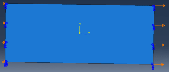
I am currently modelling a plate with 3D elements (just 1 element thru thickness):
123_fgaezf.png


I have applied a displacement BC on the right surface, as well as restraining moments. I have fixed the left face as shown in the image above.

I am looking to determine a stress vs strain plot, as per this thread. similar to what you get from testing

However, I'm not sure how I would go about this problem on my side, due to the moment constraints on the RHS surface.

Therefore, I have currently output the nodal force at a location on the RH face with time and multiplied it with the total number of nodes on the RH face (to get the total nodal force as a close approximation). I then divide this total nodal force by the area to get the stress on the RH face. I have then output displacement at that node with a function of time, and can convert this to strain via post processing.

What do you think of this method? The reaction force and Ux displacement is constant on the RH surface due to the applied BC.

Any suggestions welcome.

Thanks
 
Replies continue below

Recommended for you

Is there a reason why you don't use 2D (plane stress) elements for this analysis ? Besides that keep in mind that solid elements don't have rotational degrees of freedom so constraints applied to these DOFs are ignored by the solver.

In order to obtain stress-strain curve for uniaxial tension case then it will be easy. You can use average stress and strain from selected elements. The same goes for displacement. If you want to calculate total reaction force, sum the RF1 for all nodes on the left surface where you applied BC in this direction.
 
Yes, there is a reason, the current framework I am running currently only works for 3D elements, hence I have only kept 1 element thru thickness.
That's correct, thanks for the reminder, I was working with shell elements, and I have just transferred the BCs to the 3D elements case.
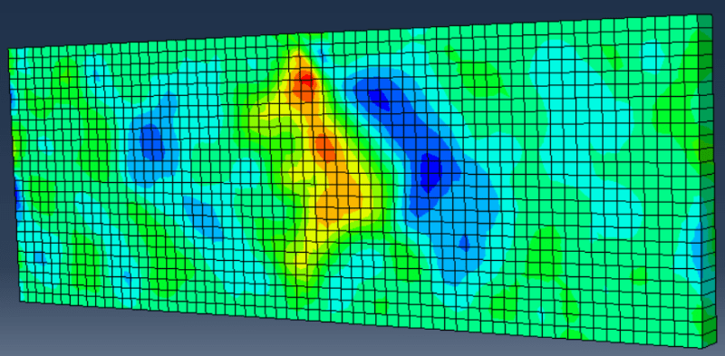
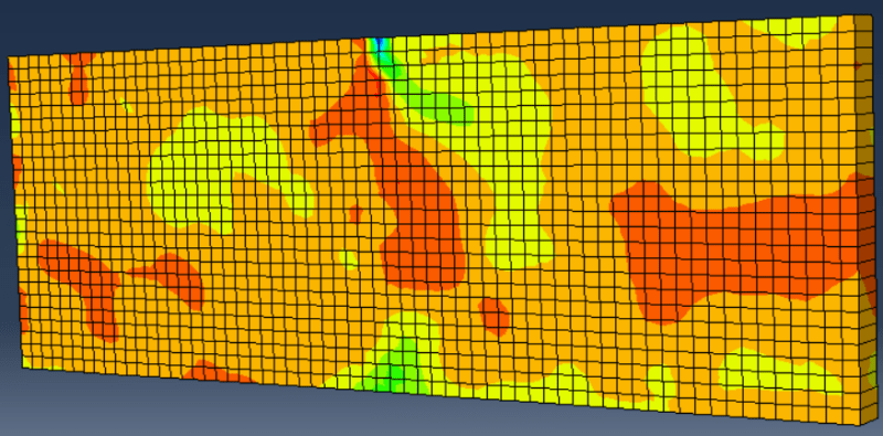
My S22 stress and E22 strain (loading direction is y) is shown below in order. Are these the ones I should be using.

124_ksjohd.png

125_sknb6y.png


Where should I be taking these elements from, the Right Hand surface? Or all elements?
How do I sum up the reaction force for all nodes per unit time?

Thanks
 
The plate is now loaded in Y direction but how is it oriented and constrained ? Can you show a picture like in the first post (with boundary conditions and coordinate system). I’m asking because stress and strain distribution looks rather unusual and it’s important for determining the location to measure stress and strain.

To sum the reaction forces you can use XY Data from Field Output, pick the nodes that are constrained and then operate on XY Data using sum operator.
 
Oh sorry, I gave the wrong image at the top, but for the contour plots below, the x and y directions are flipped (wrt to the first post).

It is a discontinous fibre filled composite, hence the weird stress field. This is why I'm having the difficulty in choosing the correct point to obtain a stress strain plot (I know post processing is required).

Essentially, the plate above is the flange of the image in this link: , akin to a flange of an IBeam which is then being pulled to failure. At the middle of the plate, there is fibre flowing into the flange, so I guess I have to choose an element/elements away from the centre of the plate (due to the web) but not to close to the applied displacement BC.

Thanks
 
In that case I would measure force and displacement and then convert it to stress and strain. Basically a virtual version of what is done in physical testing. You can measure total reaction force in the loading direction as I described previously (sum of RF2 for all constrained nodes).
 
I think I understand the method, but to confirm, I should do this (extract Force and displacement) for all nodes on the RHS face.

Why can't use use S22 and E22 that ABAQUS outputs? Is it because you essentially lose information.

 
Reaction force can only be obtained from the constrained face. Displacement can be measured at any representative point. In this case measuring stress and strain directly will be difficult due to nonuniform distribution of these variables. Hence the use of overall force and displacement for the sample.
 
I will undertake this study and let you know, thanks.

I assume I need to go into the Data Manager and average all of the nodal forces on the constrained face?
 
You can either request history output of RF2 for nset consisting of all constrained nodes (you will have to run the analysis again though) or use Create XY Data --> ODB field output, pick RF2 variable and select these nodes.
 
Thank you, this was fine.

The result of this analysis resulted in a linear-elastic response, however I expected some sort of plasticity involved. What could be the reason for this?
 
Did you define plastic behavior in the material editor ? It's necessary if you want to get plastic deformation. If you already have plasticity defined in the model and still don't see any yielding then you may have to check the units, adjust material properties or increase load.
 
I will take a look, but I dont think so. I know the analysis aborted after 20 increments
 
Status
Not open for further replies.

Part and Inventory Search

Sponsor