Continue to Site

Eng-Tips is the largest engineering community on the Internet

Intelligent Work Forums for Engineering Professionals

  • Congratulations waross on being selected by the Eng-Tips community for having the most helpful posts in the forums last week. Way to Go!

Abaqus Subroutine to remove element after each increment 1

Status
Not open for further replies.

iamoxygen

Mechanical
Jul 24, 2015
14
Hello everyone,
I am writing a user subroutine in Abaqus to remove element that has reached damage criteria ( as a function of max principal stress and strain ). I knew how to use URDFIL to read data (stress/strain) in integration points of C3D element so I am wondering if there would be a way/routine to set state or status of failed elements in next increment to be deleted/deactivated. I am working with Abaqus/Standard.
Thank you very much.
 
Replies continue below

Recommended for you

Element deletion can be controlled via UMAT subroutine. You just have to specify the number of state variable controlling this:
*DEPVAR, DELETE=variable_number

This is described in the "User-defined mechanical material behavior" chapter of the documentation (paragraph titled "Deleting elements from a mesh using state variables").
 
Thank you. I found the tutorial to delete element using state variables with Abaqus/Explicit only. I want to remove element in the same way it does with *Model change option in the input file without developing material model by UMAT.
 
If you don’t want to create UMAT there’s still an option to specify your own criterion for element deletion using (V)USDFLD subroutine. I know that VUSDFLD (Explicit) can do it (there’s even an example on github) but I think that USDFLD (Standard) will also work. At least in newer versions of Abaqus.
 
I did a code with USDFLD and DEPVAR. I set state variable to control element deletion as 2. If criterion has reached, I set STATEV(2) as 0 to flag the material point to be deleted. But somehow the values of STATE(2) in my ODB file are not only "0" and "1".
 
I want to get maximum principal strain, from Abaqus Document, which LEP. When I used GETVRM to get that value, I am not sure whether ARRAY(1)is the value I want.
 
When it comes to the first issue (values of STATEV other than 0 and 1), I guess that you have something like that at the end of your code:

if (calculated_value > admissible_value) then
STATEV(2) = 0
end if

In such case you can try this:

if (calculated_value > admissible_value) then
STATEV(2) = 0
else
STATEV(2) = 1
end if

For the second problem (with GETVRM), if you request LEP in this utility routine you will get 3 values out of which ARRAY(3) will contain maximum principal stress (LEP3).

Could you share your subroutine’s code here ? It would be easier to provide further help.
 
I am so thankful to your instant help. I alse found ordering of LE variables.
Here is my code
SUBROUTINE USDFLD(FIELD,STATEV,PNEWDT,DIRECT,T,CELENT,
* TIME,DTIME,CMNAME,ORNAME,NFIELD,NSTATV,NOEL,NPT,LAYER,
* KSPT,KSTEP,KINC,NDI,NSHR,COORD,JMAC,JMATYP,MATLAYO,
* LACCFLA)
C
INCLUDE 'ABA_PARAM.INC'
C
CHARACTER*80 CMNAME,ORNAME
CHARACTER*3 FLGRAY(15)
DIMENSION FIELD(NFIELD),STATEV(NSTATV),DIRECT(3,3),
* T(3,3),TIME(2)
DIMENSION ARRAY(15),JARRAY(15),JMAC(*),JMATYP(*),
* COORD(*)
open(unit=16,file='pvalue.dat',status='old')
!write(*,*) 'called now'
!write(6,*) 'called now'
!write(16,*) 'CALLED NOW'
C
! Absolute value of current strain:
CALL GETVRM('LEP',ARRAY,JARRAY,FLGRAY,JRCD,JMAC,JMATYP,MATLAYO,LACCFLA)
EPS = ABS(ARRAY(3))
! Maximum value of strain up to this point in time:
! CALL GETVRM('SDV',ARRAY,JARRAY,FLGRAY,JRCD,JMAC,JMATYP,MATLAYO,LACCFLA)
! EPSMAX = ARRAY(1)
! ! Use the maximum strain as a field variable
! FIELD(1) = MAX( EPS , EPSMAX )
! Store the maximum strain as a solution dependent state
! variable
FIELD(1)=EPS
STATEV(1) = FIELD(1)
IF (field(1). gt. 0.0195) THEN
IF (STATEV(2).NE.0) THEN
STATEV(2)=0
WRITE(16,*) 'ELEMENT ', NOEL, 'DELETED AFTER INCREMENT', KINC, '.'
END IF
END IF

! If error, write comment to .DAT file:
IF(JRCD.NE.0)THEN
WRITE(6,*) 'REQUEST ERROR IN USDFLD FOR ELEMENT NUMBER ',NOEL,'INTEGRATION POINT NUMBER ',NPT
END IF
C
RETURN
END
 
I’m glad that I can help. And thanks for sharing your code. Does it work as expected after the changes ? Are elements properly deleted ?
 
Yes, the elements has been deleted. I am simulating a tensile test of a specimen with Abaqus Standard. But when it has broken into 2 pieces, the solver cannot continue the next increment.
 
Convergence difficulties might occur in Abaqus/Standard once the sample is broken into two pieces. Is it necessary for you to continue the analysis after it happens ? If it’s static analysis you can try with automatic stabilization in step settings. This may help.
 
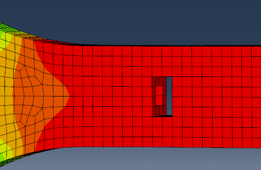
image_vtigjy.png

Even when a few elements have been deleted like this picture, the solver cannot continue. The plastic property of material is:
*Plastic
100.012, 0.
110.061, 0.00032
120.788, 0.00058
130.379, 0.00091
140.082, 0.00133
150.12, 0.00188
160.26, 0.00262
170.217, 0.00356
180.139, 0.00486
190.043, 0.00667
194.299, 0.00804
195, 0.3
 
I’ve seen a similar issue in tensile test simulation with built-in damage criterion. Adding automatic stabilization in step settings helped the analysis go further, up to the point where fracture propagated through the entire cross-section. This I think that this is the best option in your case as well. Just make sure that it doesn’t affect the results significantly.
 
I am quite new to that option. I see 2 sub-options (energy fraction, damping ratio) in Step Edit Dialog. Can you suggest me which option I should use?
 
In most cases I use the default one:

Specify dissipated energy fraction: 0.0002
Use adaptive stabilization with max. ratio of stabilization to strain energy: 0.05

In keywords this is:

*Static, stabilize=0.0002, allsdtol=0.05

But *Static, stabilize will provide the same effect.

You can adjust the parameters if it turns out that the default ones are not sufficient but it’s rarely necessary to do it.

 
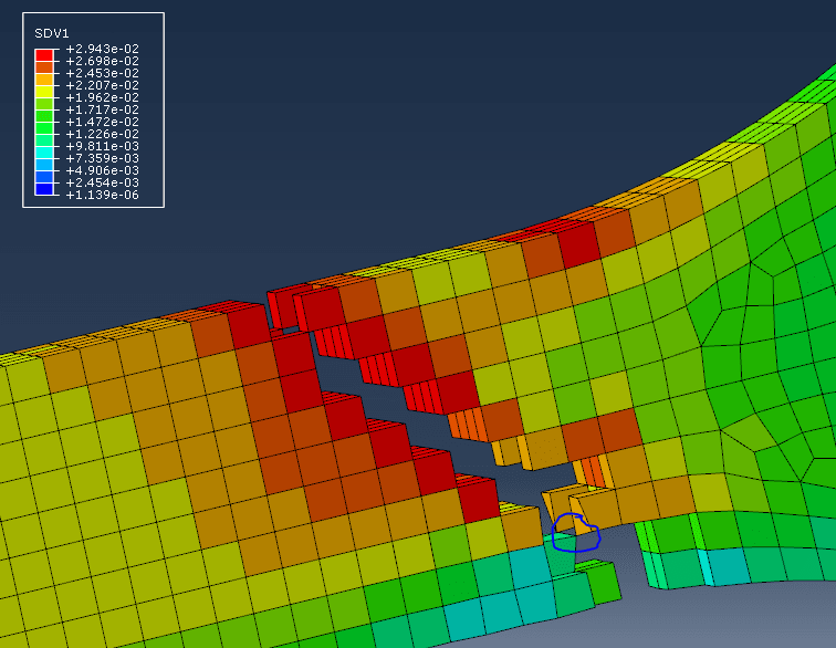
image_h9a7cy.png

Oh yes, thank you so much. I've got this after adding the keyword. You can see in picture focusing on blue mark, 2 brick elements now sharing one node so they will be highly distorted in next increment.
 
Status
Not open for further replies.

Part and Inventory Search

Sponsor