Bojana_Hepp
Civil/Environmental
Hello.
Linear static analysis in question.
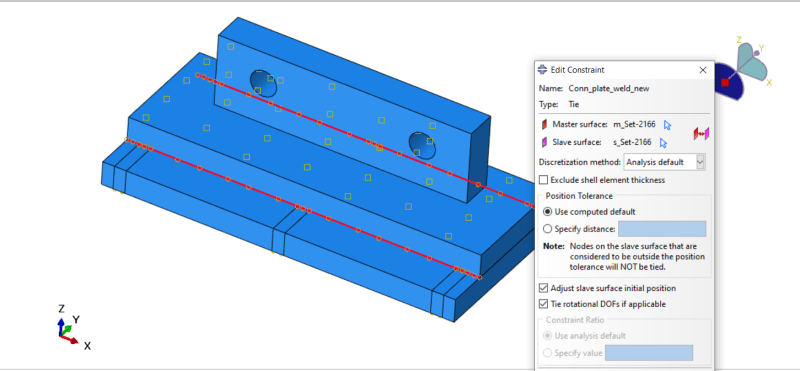
I modelled a fillet weld connection between two plates by using tie constraint (3d solid geometry). Tie constraint is established along a line on both plates, different parts, but touching in Assembly mode. Nodes are almost a perfect match on both plates. Option to adjust the nodes in initial position is set to off.
What I am interested in, is, whether the free body cut forces along these lines are representative of the real loads transferred by the weld? I am currently extracting FBC forces along 6 x elements, 10 mm in size. Plate is 40 mm thick.
My understanding is that tied nodes have their dofs exactly the same. The only thing where I can get the error is due to the mesh discrepancy between the parts?
Can I see the tied node pairs?
In addition, there is some difference in FBC forces if I generate FBC on 2d element edges compared to when I generate FBC forces on the nodes of 3d solid elements. Does anyone have the idea why?
Thank you for your help.
Beginner
Linear static analysis in question.
I modelled a fillet weld connection between two plates by using tie constraint (3d solid geometry). Tie constraint is established along a line on both plates, different parts, but touching in Assembly mode. Nodes are almost a perfect match on both plates. Option to adjust the nodes in initial position is set to off.
What I am interested in, is, whether the free body cut forces along these lines are representative of the real loads transferred by the weld? I am currently extracting FBC forces along 6 x elements, 10 mm in size. Plate is 40 mm thick.
My understanding is that tied nodes have their dofs exactly the same. The only thing where I can get the error is due to the mesh discrepancy between the parts?
Can I see the tied node pairs?
In addition, there is some difference in FBC forces if I generate FBC on 2d element edges compared to when I generate FBC forces on the nodes of 3d solid elements. Does anyone have the idea why?
Thank you for your help.
Beginner