Continue to Site

Eng-Tips is the largest engineering community on the Internet

Intelligent Work Forums for Engineering Professionals

  • Congratulations KootK on being selected by the Eng-Tips community for having the most helpful posts in the forums last week. Way to Go!

About releasing Minor moment (My) in column (I section) 1

Status
Not open for further replies.

Arbu

Structural
Mar 25, 2018
69
Dear All,

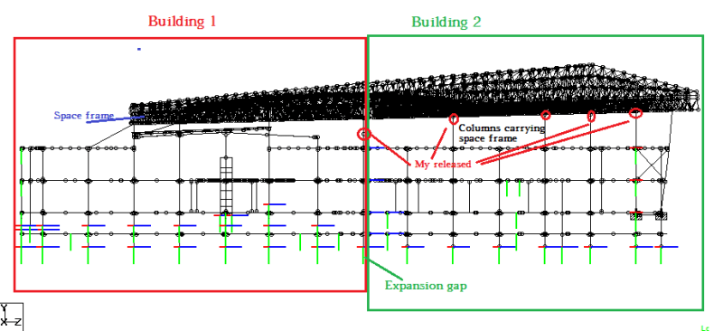
I am designing s Space frame which is having an oval shape opening, due to opening space frame is behaving like cantilever. That's why to provide good stability we provided cantilever truss from columns as shown below. The space frame is supported on truss as shown below. Here steel columns are by other steel contractor.
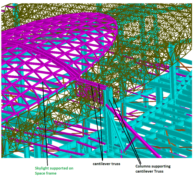
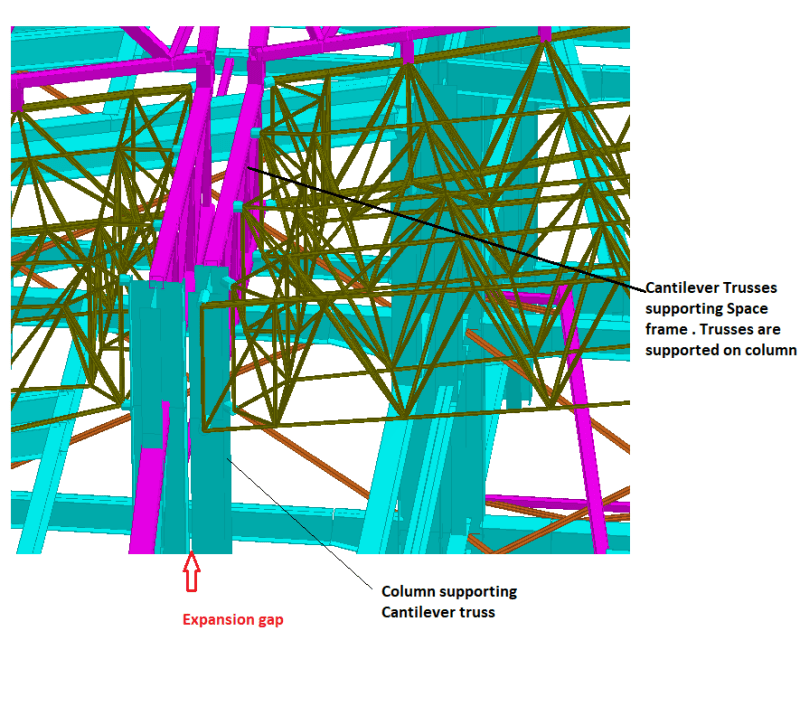
My4_ggcsei.png


My3_c4v9rv.png


For checking design of our space frame we analysed our space frame model by superimposing on steel column framing model. But we found that there is considerable minor moment (My) on the Columns at the point of connection with truss. But to pass the columns steel contractor has released My moment through full height of column.
when I asked about releasing My then he replied "it has been assumed that lateral loads will be carried by bracing". then I shown him there is no bracing along minor axis, then how lateral load will transfer to the lower level without generating bending My in the column.
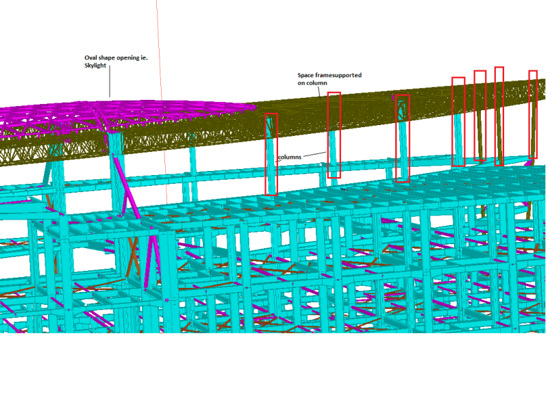
My1_f6gikw.png


Might be is trying to considered stiffness of our space frame in carrying lateral loads.

My doubts are
1. Is this practice is safe?
2. as the column is continuous (without any splice or pin at location of release) there will be some My in column but actually he is wrongly modelling the release
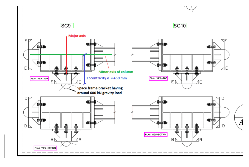
3. Apart from lateral loads if u see the connection of space frame and column there is a eccentricity of 400-450 mm, and this will create minor axis bending moment in column due to gravity load. how this My will be carried or transferred.
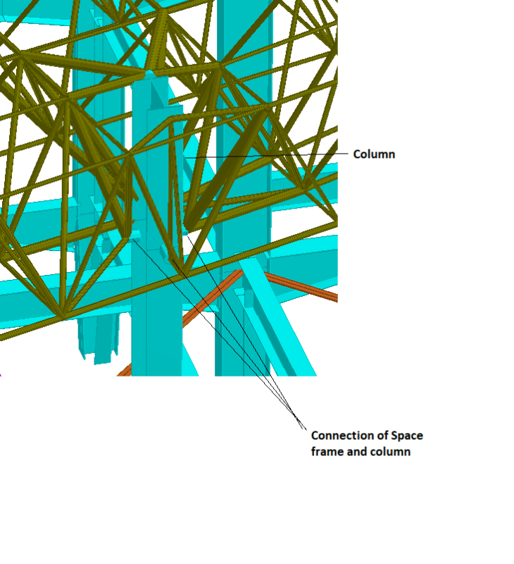
My2_sddegc.png
 
Replies continue below

Recommended for you

That is a pretty cool project! I guess everyone is too dazed to respond so...here goes nothing!

Not easy to understand what is going on but, I tend to agree with you.

As there is no apparent vertical bracing in the column plane ALONG the length of your truss, I do not think releasing the minor axis moment is justifiable. While the space frame will act as a "diaphragm" of sorts, that lateral load still has to be transferred to the ground somehow. Do you have any horizontal supports / shear walls / bracing somewhere off the images you provided? Otherwise, you are right and something will have to be done to support / transfer that moment to the ground. Could some of the columns be rotated so that the minor axis moment is taken by the strong axis? Otherwise, bracing might be the only option.

 
But we found that there is considerable minor moment (My) on the Columns at the point of connection with truss. But to pass the columns steel contractor has released My moment through full height of column.

Pretty confusing statement to me: how exactly is a contractor putting a release in the model? Are you the engineer or is he?

My doubts are
1. Is this practice is safe?

It's not a question of safety....but one of accuracy. If you have a cantilever there.....what sense does it make to have a release?

3. Apart from lateral loads if u see the connection of space frame and column there is a eccentricity of 400-450 mm, and this will create minor axis bending moment in column due to gravity load. how this My will be carried or transferred.

I would think if you can't have any minor axis bracing at the level of the cantilever truss.....then perhaps the answer is to have it below this level. (If the stresses and displacements are acceptable above.)

 
OP said:
then how lateral load will transfer to the lower level without generating bending My in the column.

Do you really want your environmental lateral loads making their way through the system via weak axis bending of these columns? I would think not.

OP said:
But we found that there is considerable minor moment (My) on the Columns at the point of connection with truss

What about your design is creating these moments? Primary lateral from environmental loads? Gravity eccentricity? Detailing, as you've shown with all the truss members coming into the column, that does not make a point of trying to limit weak axis bending in the columns. Frankly, I would think that all of these moment sources would be quite resolvable if one approaches the design with that goal in mind. In this respect, I'm with your contractor on this.

Obviously, weak axis moments that fall out of your analysis and cannot be eliminated by intelligent detailing must be dealt with. Additionally, the column will have significant strong axis bending which may create a demand for weak axis / torsional bracing to address plain old weak axis buckling and lateral torsional buckling.

It might be useful for us to see the entirety of this structure to get a sense for the intended lateral system as a whole. From what I see, it appears to me that the structure is intended to be supported by vertical trusses at four strong points located at the quadrant junctions. If that's the case it may only be necessary for diaphragm torsion to be resisted by weak axis column flexure.
 
Thanks for the reply.


My doubt is apart from environmental load there is considerable eccentricity for gravity loads, which will result in My moment. Now if there is My moment on column due to gravity load and we are releasing it, does it makes sense?? I am not that much experienced person in framed and braced building. Please explain. full side view of building has been attached. Columns are having no bracing along the length of the building.

full_side_view_qv4g1a.png
 
The only way there is a release of sorts is if the capacity of the continuous member is overcome and a plastic hinge forms. If there is a 'pin' at the top and a hinge at the base and no other lateral load resisting system then you have a ductile mechanism. Whether it continues to rotate until collapse partly depends on the structure restraining the top of the columns and the nature of the load.

You cannot arbitrarily release all moment in a continuous member as it simply does not reflect the reality of what is occurring, the member will see load until its capacity is exceeded.

Their model for example might need to model the continuous columns several storeys down the structure with support at floor levels to correctly deal with the stiffness and distribution of loads in the columns when the roof load is applied. If they are getting a large moment then it needs to be dealt with appropriately through design and detailing, putting your head in the sand as a designer and releasing a design action which is essentially telling you the member is failing/buckling it is kidding yourself. Any modelling needs to reflect the actual boundary conditions & constraints that are present in the real world.
 
I'm not clear what's physically being described. It looks like the releases are generally at the tops of columns. Is this just a question of whether it's a fixed connection or a pinned connection? Where does releasing those moments make the load go? It might or might not be reasonable depending on the detailing and the load path.
 
Presumably if you pin those connections and the system is still stable, the space frame above is able to take the moment from the eccentricity internally and resolve it into a couple between the various supports.
 
Dear Agent666,

I am agree with you, as there is no such detailing which is releasing the moment My in column, so minor moment release should not be there. There is a considerable eccentricity for gravity loads , this point i notify to contractor. Now he agreed to remove My release and he will design for My moment, might be he will go with Star column.
 
In your last picture in your first post, I'm not seeing the eccentricity that's going to definitely cause a moment on the column (i.e. a structural system with an eccentric moment on the column isn't strictly necessary for stability of the system under gravity). You have a single load point on either side. There's an offset between the web and the node point in the spaceframe, but there's a number of ways you could treat that eccentricity, some of which would be stable while assuming pure vertical reaction from the column.

When you're saying moment release, what do you actually mean? Is there a moment release at one node? A few nodes? Where are they? Where did the lateral loads go when those nodes were released.

If you're actually talking about the top points in those columns, like you circled, I can think of a number of ways to legitimately use pinned connection assumptions to help model some of the stuff going on at the top of your column.

There's really not context to understand what the structural behaviour and assumed load paths are.
 
Dear TLHS,

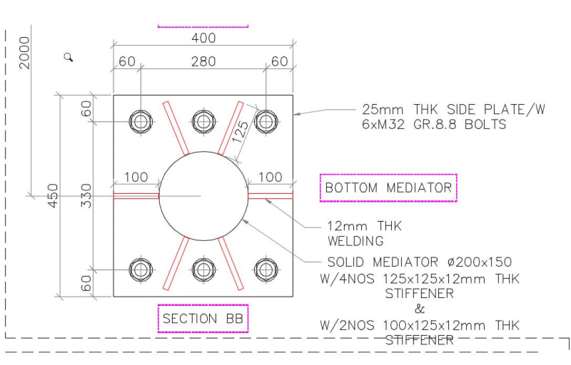
please see the plan of connection of column and space frame bracket. There will be Moment My due to eccentricity My = 600 x 0.45 = 270 kN-m . Now if someone is releasing minor moment My in model, then how will be the behaviour of column. There is a minor moment and if someone is releasing it. is it a safe practice?

my_c2sjtt.png

my2_xqno0r.jpg


Or if u know some detailing to avoid this Moment My then please let me know. I need to keep bracket well out of column otherwise my space frame members will clash with column flange.
 
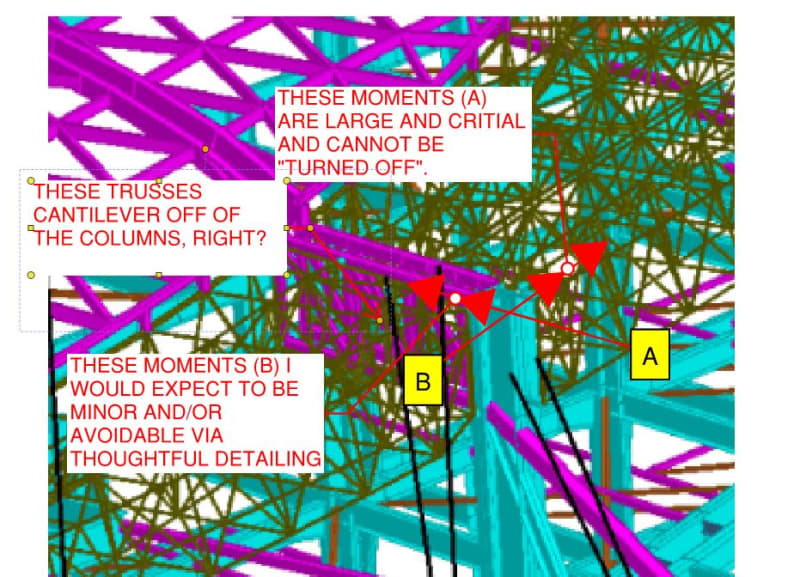
I can only speak for myself but, what I think is preventing a definitive answer from materializing here is confusion over what exactly your system is and which direction is "My" in your global model. To that end, please review the sketch below and comment accordingly as to how well I've interpreted your situation.

Nobody can just wish away meaningful forces from your structure. You'll need to arrive at one or the other of these conclusions:

1) Adjustments can be made to your model or detailing such that My really will be negligible OR;

2) You're stuck with the My moments that you've calculated and they'll need to be resolved in the column design.

OP said:
Now if someone is releasing minor moment My in model, then how will be the behaviour of column.

The analysis of the column in your model will be hopelessly incorrect unless it reflects the reality of the structure.

OP said:
Is it a safe practice?

The only safe practice is for your model to accurately reflect the reality of the structure.


c01_ofi432.jpg
 
Status
Not open for further replies.

Part and Inventory Search

Sponsor