Continue to Site

Eng-Tips is the largest engineering community on the Internet

Intelligent Work Forums for Engineering Professionals

  • Congratulations waross on being selected by the Eng-Tips community for having the most helpful posts in the forums last week. Way to Go!

above ground pipeline deflection issue 1

mahmoud kassab

Mechanical
Oct 24, 2023
7
greetings all,
i have a pipeline 1700m size 10in and wall thickness 12.7mm its condition is laid aboveground on concrete sleepers with intervals every 15m the pressure is 82bar and temp 85c the main issue here is due to the client requirement and site issues using any loops with hot bends or even zigzag configuration with cold bend are not permitted after analyzing the pipeline it gives at the change directions bends (2 bends 21deg and 32deg) which are of cold bend type with radius 40D because also the hot bend for changing direction is not allowed, the deflection (displacement) at the bends body reached 1m laterally we tried to put anchor blocks to reduce it but it had load 150ton which is a huge load to design anchor block (4m*4m*4m) so even the anchor blocks is not a solution the question here is 1m deflection at bend body is acceptable noting that:
1- the supports are not an issue we will make it wide enough to let the pipe move freely on it
2- the max stress ratio from CAESAR analysis is safe 82% for all cases even the expansion case
3- my main fear and concern here is the strain as far as i know CAESAR is single beam theory software and doesn't commodate any effect of strain and the 1m deflection in the bend body could cause work hardening making the material to behave more brittle and fail due to crack which caeser is limited software to check such effect and need to be studied using Abaqus FEA ,is my concern valid or not and based on experience what is the value of maximum deflection allowed for the pipeline as there is no standard or company spec state such value for pipeline all have only for piping which ranges maximum from 120 to 150mm
 
Replies continue below

Recommended for you

Well someone is being ridiculous here.

1700m with an op temp of 85C is going to get a LOT of expansion and if you're above ground this thing will snake and buckle more than anyone would believe.

The support spacings look quite along way apart as well. you will or could get a lot of friction on those types of supports so the pipe could easily buckle horizontally or vertically before you get to a bend.

A 1m movement may not be so bad, but depends on how you contain it and how the movement is spread out from the bend itself.

Angle bends between 20-40 degrees often get the highest stress as they take a lot of axial load as well as the bending stresses.

Which idiot in the client is saying no expansion loops or zig zags? or Hot bends?

Got a 3D sketch of this?

Remember - More details = better answers
Also: If you get a response it's polite to respond to it.
 
the span of supports is not long as we started with 10m intervals and resulted 1mm vertical deflection so we decided to increase it to 15m it resulting of 4mm vertical deflection, secondly it will not buckle or snack around before we reach the bend because guide supports are distributed evenly along the route 2 rest support then 1 guide also a 4 limit stops has been used to guide the axial displacement to the bend the axial limit stop load is 4.5ton, lastly why the client refuse the expansion loops and hot bends because the project is critical in time and the site doesn't want to wait the lead time of hot bends as for the zig-zag it refuse it as the first initial trial resulted in 10 zig-zag configuration (every 150m) to result in only 15cm deflection but the site refused such configuration for lack of construction experience,
my last question you stated (A 1m movement may not be so bad) why and how it is not so bad, my concern from material POV (cause work hardening making the material to behave more brittle and fail due to crack) isn't valid?
 
1m in 1700 = strain of 0.0006 m/m. This is not excessive in a straight run of 1700m. However a 1m movement at a bend may induce considerable bending in the connecting pipe. It is important to understand the possible effects there. What does the connection to the rest of the piping look like where this 1m movement of pipeline is being observed?

--Einstein gave the same test to students every year. When asked why he would do something like that, "Because the answers had changed."
 
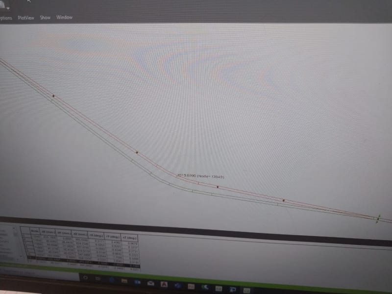
WhatsApp_Image_2024-10-01_at_3.36.49_PM_xbwrw9.jpg


no the 1m not for 1700m pipeline it is in a short span again because I use guide to restrict the lateral movement see the attached photo this is from the analysis and the amplification factor for displacement is 1 so as shown the 1m deflection in the bend body itself and at the two rest supports that adjacent to the bend then it decrease to .5m for the second support then eliminate at the guide support so basically the 1m deflection is in the bend body itself 12m at maximum
 
even if this pipe is very flat, this is something which in practice simply will not work long term, especially if the pipeline cycles between hot and cold. This is very important to understand as whatever they tell you about the number of cycles, multiply by at least 10 if not 100 for what happens in reality.

Your guides will need to be really quite strong to stop movement and you will need to look very closely at the friction factor you use for the supports and look at the impact if that changes over time.

The danger is that the expansion force and movement end up being a lot more concentrated that your model predicts or the expansion appears in a different place.

Remember - More details = better answers
Also: If you get a response it's polite to respond to it.
 
As far as i know CAESAR takes the cycles especially for expansion case number of cycles equivalent to 2 cycles a day for 20 years and this is more than enough for my case and I checked the loads on guides it is not significant value at the end what is your recommendation as from my POV I refused to accept such case of deflection and limited it for 20cm maximum and if can't be achieved by any means the pipeline to be buried
 
Caesar defines the default number of cycles as 7,000 which lines up with B31.3 code assumptions. Its on you the designer/engineer to correct it if that's not accurate.

Vertical deflection is not the only criteria for support spacing and given you're putting it on sleepers, it seems ridiculous to stretch it out to 15m for no reason?

As others have said you need to reevaluate the support spacing and types to better handle the expansion and loads you have.
 
The strain does not happen in the bend alone. The strain is still small m/m. You simply see the total at the bends, but it happens m/m. At the bend, the displacement induces different bending strains and stresses, but you say it passes allowable stresses. If strain is high there, check cyclic strain hardening there at the bend only. If it passes stress, you likely have low strain. If strain is very low, work strain hardening = force x strain/ time, accumulating enough work to do damage will take a very long time to develop, even with lots of cycles.

--Einstein gave the same test to students every year. When asked why he would do something like that, "Because the answers had changed."
 
stretching the spans to 15m to decrease the number of supports used and as far as I know the span is only to be verified with vertical deflection and the total stress induced due to the bending caused by spanning and in my case both are more than safe however still I have doubt for the huge lateral expansion and foe noting the spacing of supports doesn't play any rule in the lateral deflection that I have
 
I agree the pipeline really should be buried to reduce these movements, though at 85C you might still find issues at the bend plus upheaval buckling issues.

But like you say in the OP - there is no defined maximum deflection beyond what any one company or person decides is the maximum.

You could have 10m if you wanted, but think in reality your supports would lock up if you have the space.

Do you have deflection / expansion at the ends?
What is the extant of your horizontal forces at the nearest support?

They would be big support to allow for the movement, but if you can get it to work then why not?

I would though do a sensitivity on the pipe to support friction factor to see what the min / max amount would be.


Remember - More details = better answers
Also: If you get a response it's polite to respond to it.
 
thanks to all,
but as (LittleInch) states there is no maximum value has been stated but I don't think the issue as problem of support you can adjust the arrangement as you like and I also checked the deflection at the end of the line it is not that much and this is because I already shift the movements towards the bends using limit stops but quoting (but if you can get it to work then why not) the answer to the why not I have fear consider the material behavior and it won't be simply approved it will not fail by simple calculation as (1503-44) suggested as I am originally material engineer and I know if you got present to high strain it could cause a lot of damage specially this strain is generated in cold bend that has been gone through plastic deformation so the grain structure from the beginning is disoriented
 
What sort of force have you on the "line stops"? In practice these often fail / fall over.

If you're still in the elastic strain zone then I think you're worrying unduly about this extra movement or stress at the bends.

Who is "approving" this?
Why is the client so anti expansion loops?

Remember - More details = better answers
Also: If you get a response it's polite to respond to it.
 
its axial limit stops have detail configurations as two supports with concrete in the middle with a gap 50mm also it is supported with v shape structure with the ground and this is my least concern as the civil team will confirm design of such support that will not fail under the supported load, secondly how I can even determine that I am in the elastic zone without performing FEA that what I am asking that caeser will not be adding value in my case, who is approving is me as I am the consultant in the project and I am searching with the engineering contractor the most applicable solution, lastly the client so anti expansion loops as I answered previously (the project is critical in time and the site doesn't want to wait the lead time of hot bends as for the zig-zag it refuse it as the first initial trial resulted in 10 zig-zag configuration (every 150m) to result in only 15cm deflection but the site refused such configuration for lack of construction experience,)
 
You are allowed to use full stops and sentences....

The stress report shows you if any part of the pipe is above the maximum allowable stress / SMYS. If not then you're in the elastic zone no?

Then bury it if you don't want a 1m expansion, but you might find the bends are overstressed when you do that. Try it and see what happens.

Above ground line stops can only handle a relatively small force - say 5kN or less - before they turn into massive anchors.

Remember - More details = better answers
Also: If you get a response it's polite to respond to it.
 

Part and Inventory Search

Sponsor