Continue to Site

Eng-Tips is the largest engineering community on the Internet

Intelligent Work Forums for Engineering Professionals

  • Congratulations IDS on being selected by the Eng-Tips community for having the most helpful posts in the forums last week. Way to Go!

AC Motor shaft sheared 5

Status
Not open for further replies.
Replies continue below

Recommended for you

How is the motor controlled?
This could be a fracture caused by "reclose effect" due to the supply being interrupted for a very short period of time and reclosed partially out of phase.
Start/delta starter, soft starter with one or more SCRs misfiring, frequent "Auto-Off_Manual switching while it is running, rapid switching from forward rotation to reverse operation.
The flux in the rotor can take more than a second to significantly reduce, so all open transition switching can result in very high torque transients.
The two weld points would probably create stress points and weak spots to transient torques.

Mark Empson
Advanced Motor Control Ltd
 
My thoughts fwiw

The description above figure 6 indicates fatigue failure from rotating bending stress. That is a pretty common failure mode, and yes it sort of resembles that (I would always defer to a materials guy and someone that looks very closely at the failure).

Location of such failure would typically occur at the location along the shaft where bending stress is maximum. IF we draw a shear and bending moment drawing based on radial load applied on the shaft extension, under a BIG SIMPLIFYING ASSUMPTION that the shaft cross section is uniform, then the max bending moment does not occur anywhere close to this location.

That suggests that the interaction between the core and shaft has some role, one of three ways I think of: 1 - a source of stress from interference; 2 - as a stress concentrator at the end of the core (*); or 3 – as an effective change in shaft diameter which invalidates the above simplifying assumption and thereby changes the location of the maximum bending stress. I’d have to try to work out a shear and bending moment diagram to see if #3 makes sense. It’s a little more complicated without that simplifying assumption, I’m not sure what that diagram would look like at the moment.

* the stress concentrator could also be those welds.

Still waiting to hear about the keyway. Certainly if the keyway stops abruptly with a squared-off fashion (rather than rounded or sledrunner) exactly at the plane of the failure, that would be a significant fact.

What is the effect of those axial grooves in the shaft? (knurling as John called it). At a minimum, they reduce the effective diameter of the shaft slightly which reduces fatigue strength slightly. But it is well known that poor surface conditions of the shaft (typically from corrosion) can reduce the fatigue strength (I guess it forms initiator locations for cracks). Could those grooves act like an extreme case of poor shaft surface condition and greatly reduce the shaft fatigue strength? John - how common is knurling of the shaft under the rotor core....and does it typically extend beyond the core as it does here? (if the purpose was to prevent relative movement, then the shaft knurling could terminate before the end of the core... a location which may see locally higher bending stress.


=====================================
(2B)+(2B)' ?
 
Just thinking out loud (broadening the possibilities, I’m not in a position to narrow them), I wonder if excessive interference between core and shaft might play a role.
I looked up the effect of interefence fit on shaft fatigue strength:
Machine Elements Life and Design said:
“A special emphasis should be placed on the decrease in fatigue strength caused by press fits. This kind of stress raiser is not connected with any change in the shaft’s shape, but it may reduce the fatigue strength even to 25–30% of that of the plain shaft. This effect is caused both by additional stresses where the hub and shaft surfaces make contact (see also Chapter 2, Section 2.1) and by fretting damage to the shaft surface layer. The formation of fretting is associated with the relative motion of the contacting surfaces under the influence of bending moments and torque. A mechanism in which this motion appears has been described in Chapter 2.”

They are talking in particular about interference between coupling hub and shaft, but the same principle should apply to a postulated interference between shaft and core.
They don’t say where the failure would occur in such case, but I’m pretty sure it’s at the end of the hub (core in this case), for two reasons:
1 - in the center of the core, the added stress is pure compression, there is no shear component from the compression. I think there is a shear component at the ends.
2 – The discussion following the above paragraph indicates some means to mitigate the problem, and it involves changing the profile of shaft or hub at the ends.

Also the fretting they mention would be most severe at the ends.

None of this considers the grooved/knurled shaft. John suggested these are not normally used with press fit / interference fit.


=====================================
(2B)+(2B)' ?
 
I think it's your 2 AND 3 at the same time Pete.

2) The stress riser due to the HAZ (Heat Affect Zone) of those welds.
AND
3) The effective change in shaft diameter where it leave the rotor... in fact almost exactly where it leaves the rotor.

Keith Cress
kcress -
 
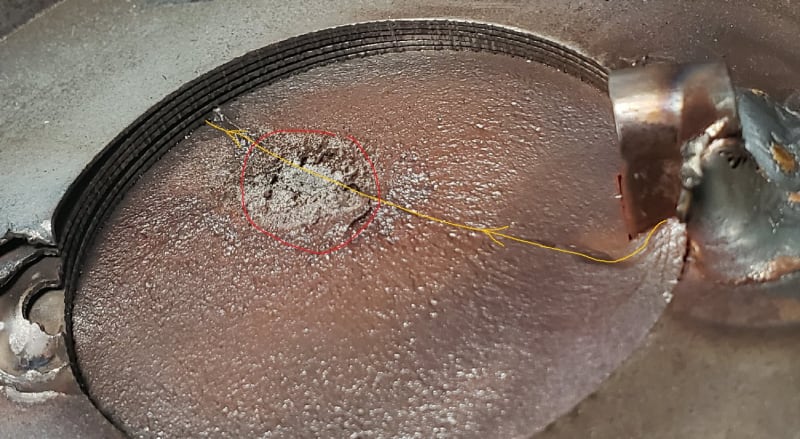
CrackedShaft_dr8zhw.jpg


Gold line start and crack propagation direction.
Red circle is the last bit holding that actually got twisted off.

Note on the terminating end of the gold crack where the shaft was punched in as the shaft bent on separation. The twist-off would happen at the 'last end' of the crack failure.

My theory anyway.

Keith Cress
kcress -
 
Thanks Keith. I didn't see that view before - now I can see there is the key sticking up at 3:00 in that photo. The top of the key is rounded and the key is welded to the core and the shaft. Please disregard all my questions about the key and keyway.

IF the propogation is in the direction you say (*) THEN it started in the vicinity of that keyway / weld.
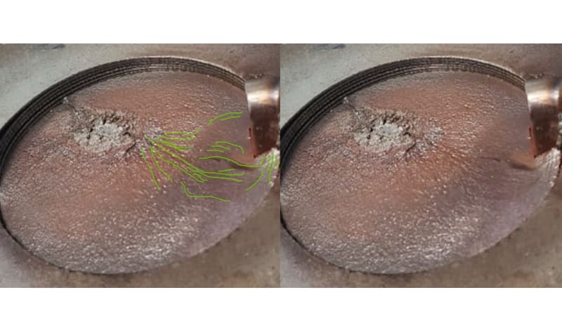
(* however, I think I can see beach marks running parallel to your arrow and I thought the failure propogates perpendicular to the beach marks ),

=====================================
(2B)+(2B)' ?
 
Nice picture Keith. I have suspected that the shaft was keyed to the rotor core as well as the press fit.
Suspicions are stronger now.
Marke and I have both suggested that the shaft was weakened by the welding and then suffered a torque event. Either by a re-closer event or by Jeff's suggestion of inappropriate breaking.

Bill
--------------------
"Why not the best?"
Jimmy Carter
 
Hi Keith

Excellent job it's the photo mark up.

Electricpete , I too struggled with the Bach marks and its possible that there was more than one crack on the outer edges of the shaft albeit that the keyway would have been the weak point especially having been welded.


“Do not worry about your problems with mathematics, I assure you mine are far greater.” Albert Einstein
 
One more data point, the inside corners of the key way do not appear radiused.

I have no reason to doubt what Keith says. But if I were investigating at our plant, I'd give it to our degreed metalurgist who dabbles in failure analysis part time. I've done that before and he comes up with some remarkable subtle observations which I would never have noticed or understood, based on both the macro appearance and the under-the-microscope appearance. We're lucky to have him.

=====================================
(2B)+(2B)' ?
 
fwiw, my best swag based on attempting to read beachmarks (which are perpendicular to direction of crack propagation) is that the cracks initiated on the inside corners of the keyway, rather than the weld (although view from the other side of the key hidden in this photo might be different). Again, I'm no expert and I would trust a knowledgeable person with closeup inspection far more.

BeachMarks2_uv5rqm.jpg


=====================================
(2B)+(2B)' ?
 
Noting the requalification of the motor being from a "traction elevator"... is the output shaft
driving a pulley, or is it directly coupled? (I may have missed that answer if it was given.)

On the knurling:
Knurling is an economical way of creating an obstructing fit between the rotor laminations and shaft.
This type of fit relies upon raising the shaft surface metal to compensate for the shaft diameter being undersized for the hole it's mating with.
Hence, the additional necessary application of weld(s) in this instance... to keep the rotor in its proper location.
Typically this type of assembly is found in much smaller horsepower arrangements.

Knurled shaft fits on larger motors are usually confined to cooling fan fits, etc.

As Marke suggests, the weld points could have contributed to creating stress points,
"but" typically weld points like this are found on many motors in industry without any adverse effect.

Another observation related to the motor's design:
It's not very often the rotor/shaft portion of an electric motor is SMALLER in diameter than its working output shafts.
(They are out there. A soaking furnace motor comes to mind to name one example.)
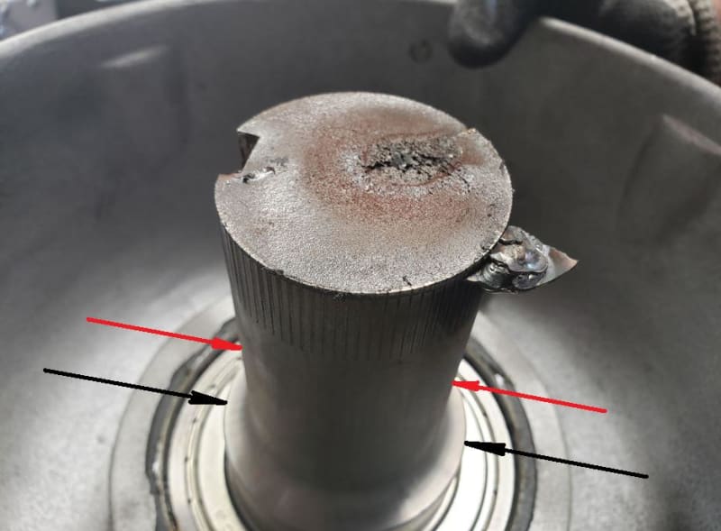
In looking at the re-attached photo from earlier in the thread, note how the rotor is
mating with a shaft that is smaller in diameter than what is passing through the light duty
6200 series bearing heading toward the brake.
Consider how much more robust the rotor portion would be if the shaft remained the same diameter or slightly larger than the brake output shaft end.

The shaft failure appears to be "text book" rotational bending.
At this point, it's conceivable that an identical motor could be reinstalled for service, and
within a period of time have the same failure.

If a new shaft was made to replace the broken one, it would serve greatly to make it a "keyed"
press fit that would bottom against a shaft shoulder and not rely upon a couple of spot welds.

With this being a somewhat OEM motor failure, I'd suggest more input from the manufacturer
of the equipment, and the maker of the motor to learn if there is something amiss here.

John

SHAFT_FAILURE_pyo36u.jpg
 
note how the rotor is
mating with a shaft that is smaller in diameter than what is passing through the light duty
6200 series bearing heading toward the [load]
Good point. (I knew something looked odd about that picture). That is opposite of the vast majority of motors (and other rotating equipment) where the shaft gets steadily larger as you move to the center. In addition to crafting a weak spot, it changes the bending moment profile along the length of the shaft (for a given assumed radial load on shaft extension)
=====================================
(2B)+(2B)' ?
 
Hi

Just looking at the photo electricpete posted on the 7th oct, it appears to me that the green lines Pete marked out actually appear to come from the silvery coloured area ( where we believe final fracture took place), I know this goes against the common thinking but I wonder if the crack started opposite the keyway and made its way across, I can see a crack in the outer diameter just above the silvery coloured area in peters photos.

“Do not worry about your problems with mathematics, I assure you mine are far greater.” Albert Einstein
 
Status
Not open for further replies.

Part and Inventory Search

Sponsor