Eng-Tips is the largest engineering community on the Internet

Intelligent Work Forums for Engineering Professionals

  • Congratulations waross on being selected by the Tek-Tips community for having the most helpful posts in the forums last week. Way to Go!

Acceptable current unbalance in three-phase motor 1

Status
Not open for further replies.

lucaspenalva

Mechanical
Oct 16, 2017
28
0
0
BR
Hello there,

What are acceptable ranges of current unbalance in three phase motor?

Considering:
current unbalance = (max deviation from average current) / average currrent

I have this motor that powers a pump:
R=87 A
S=91 A
T=88 A
AVERAGE = 88,7 A
MAX DEVIATION FROM AVERAGE = 2,3 A
CURRENT UNBALANCE = 2,3 / 88,7 = 2,6%

Is this normal?
 
Replies continue below

Recommended for you

That's not too bad.
For an evaluation on the effect on the motor you must consider that heating is proportional to the square of the current.
Take the RMS of the three currents.
87[sup]2[/sup]= 7569
88[sup]2[/sup]= 7744
91[sup]2[/sup]= 8281
Sum of the squares = 23,594
Root of 23,594/3 = 88.68 Amps
If this value is greater than the rated current of the motor you can expect the motor to overheat.
For large values of unbalance there will be rotor heating.
This heating will be reflected in the line currents.
You cannot generate heat without energy input.
However the cooling of the rotor may be compromised.
It depends on the rotor design.
Rotors with a fan cast integrally with the squirrel cage will cool the rotor much more efficiently than rotors with a shaft mounted fan.
Fortunately, while an overheated rotor is not good, it is not as serious as overheated windings.
Unbalanced currents are an effect of unbalanced line voltages.
The percent current unbalance is always worse than the percentage voltage unbalance.

Bill
--------------------
"Why not the best?"
Jimmy Carter
 
@waross

Thanks for your input !!

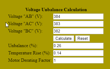
Here's measured voltages:
R-S = 384 V
S-T = 383 V
R-T = 382 V

That's 0,3% unbalance.

Therefore current unbalance is 8,7 times greater than voltage unbalance (= 2,5% / 0,3%).
I've looked up that current unbalance can reach up to 10 times voltage unbalance. Is that correct ?

You said "Unbalanced currents are an effect of unbalanced line voltages.".
But is it possible to have balanced line voltages and still unbalanced currents due to problems related to motor itself (example, windings)?

Is there any benchmark on acceptable ranges for unbalanced current?

How big unbalance is to be a concern?

 
Yes, the winding's are not exactly identical so some imbalance is expected.
Likewise the phases are often slightly different.
We used to play with swapping phases to improve balance (3,000V motor on a 12,000' line).
Your balance does not look bad.
As Waross suggests check temps, that is the real key.


= = = = = = = = = = = = = = = = = = = =
P.E. Metallurgy
 
NEMA MG1 standard gives a maximum allowable voltage imbalance of 1%. If current imbalance exceeds 10%, the motor must be derated.
 
I've looked up that current unbalance can reach up to 10 times voltage unbalance. Is that correct ?
Yes, at full load. At no load current unbalance can be up to 20 times voltage unbalance.
(voltage unbalance causes a current unbalance in the magnetizing portion of the current.... that becomes a smaller fraction of the total current as we add load current)


I don't consider your readings unusual or alarming based on the info given.

=====================================
(2B)+(2B)' ?
 
Old rule-of-thumb given to me by my J-man 40+ years ago when I was an electrician at a steel mill; for every 1% of current imbalance, motor heat increases by 5%. So in your case, the motor temperature would be 13% higher than it would be without the imbalance. Whether or not that is dangerous to your motor is a factor of how loaded it is to start with and any other factors leading to motor heating. The other part of his rule was that for most common applications, anything under 3% is tolerable, 4% or more requires de-rating of the motor by the percentages above, so a 5% current imbalance means having to de-rate the motor output by 25% if you don't want it to burn up under full load.


" We are all here on earth to help others; what on earth the others are here for I don't know." -- W. H. Auden
 
lucaspenalva
What is the full load Amps from motor-nameplate?
In your case the voltage measured can not be cause of high current imbalance.

volt_olmc8i.png


lucaspenalva said:
But is it possible to have balanced line voltages and still unbalanced currents due to problems related to motor itself (example, windings)?

Yes, due to problems related to motor-winding itself ( even when the turns per phase are equal), as well due to supply polution caused by lot of VFD-s and similar devices.
You should determine whether the current imbalance is because of winding imperfections or supply polution.
More at
 
Hello there guys, thank you all for your inputs so far!

It's a 60 HP motor (nominal current @380V = 84,5 A).

So to check the cause of current unbalance, I should then swap phases and see:
-if current unbalance is still present in the same motor phase, its a winding/motor problem;
-if current unbalance is at the same supply phase, then its a supply problem.

correct?

I'm struggling to find formula to calculate expected current unbalance due voltage unbalance. Does any one know how to ?

Then it would be easier to find out if its supply or moto/rwinding problem.

Example:

1% supply voltage unbalance causes 10% current unbalance.
But measured current unbalance is 15% (which is > than the expected 10%), so i'd know i have a motor/winding issue.
 
What is your rated full load Amps?
The RMS of the individual line currents must be less than the rated FLA.
How much less is a matter for judgement based in part on the method of cooling the rotor.
The ambient temperature is also a factor.
Epete said:
Yes, at full load. At no load current unbalance can be up to 20 times voltage unbalance.
(voltage unbalance causes a current unbalance in the magnetizing portion of the current.... that becomes a smaller fraction of the total current as we add load current)
A common cause of current unbalance on a perfectly balanced supply is a slight eccentricity of the rotor.
In practical terms, I would be happy to see the currents match so closely on a motor in the field.
By the way, how are the currents measured?
Clamp on meters and doughnut CTs can easily show that much error due to the positioning of the conductor in the window and due to magnetic influence from adjacent conductors.
OP said:
Is this normal?
If your rated FLA is 90 Amps or above I would not worry.

Bill
--------------------
"Why not the best?"
Jimmy Carter
 
> I'm struggling to find formula to calculate expected current unbalance due voltage unbalance.

you had it right in the beginning, current unbalance is expected to be 5-10 times voltage unbalance at full load, and even higher at lower load.

if you want a formula, look for the negative sequence impedance of the motor expressed as a p.u. (multiple of full load impedance). it is in the neighbourhood 5-10 (*). Also the unbalance is a good approximation of the p.u. negative sequence under typical conditions. if your negative sequence impedance is 8p.u, then 1% voltage unbalance will give approx 8% current unbalance at full load and even higher current unbalance at lower load.

(*) By the way there is a somewhat loose physical reason that the pu negative sequence impedance is the same general ballpark as the pu locked rotor impedance (which is the number that most people know as the ratio of starting current to full load current... 6-9 or whatever). they both represent an extremely high slip condition (albeit negative sequence slip with motor at nameplate speed is almost twice as high as locked rotor slip). I'm not saying that's exact, but it's a reasonable way to start thinking about it imo

=====================================
(2B)+(2B)' ?
 
Pete; the current is a function of the motor impedance in relation to the supply impedance among other factors.
There is a lot of similarity in the action of a motor and the action of a grounded wye/delta transformer.
Both transfer power from the high phase(s) to the lower phase(s).
The higher current taken by the high phase tends to lessen the current that would otherwise be taken by the lower phase.
A suggested method of solution.
Compare the directed differences between the symmetrical back EMF and the applied unbalanced voltages.
A note: while phase angle errors often accompany unbalanced voltages, it is geometrically impossible for line to line phase angle errors to accompany balanced line to line voltages.
Balanced line to line voltages must form an equilateral triangle which implies equal phase angles.

Bill
--------------------
"Why not the best?"
Jimmy Carter
 
Hi Bill
the current is a function of the motor impedance in relation to the supply impedance among other factors.
Let's say the voltage unbalance originates upstream of the relevant supply impedance. Then I would think that fractional effect upon unbalance current due to supply impedance is on the same order of magnitude as the fractional effect on motor starting current due to supply impedance (typically 10%, 20% or 30% unless it is a really weak power system… which I have had no exposure to working in a power plant). Here's my logic for predicting the effect of power supply impedance in reducing current unbalance is similar to the effect of power supply impedance in reducing starting current...

Any zero sequence impedance won’t enter into the problem because motor only sees phase to phase voltages whose vector diagram forms a closed triangle with no zero sequence (and I'm asusming voltage unbalance is calculated from phase to phase measurements). And the ungrounded wye connection of the motor prevents any zero sequence currents.

So the supply system impedance relevant for evaluating unbalance current flowing in repsonse to unbalanced voltage is the negative sequence impedance. For transformers and cables the negative sequence impedance is roughly the same as the positive sequence impedance (these devices react the same to negative sequence as they do to positive sequence, unlike the motor when spinning forward).

So unbalance voltage sees a comparable supply impedance (the negative sequence) to the normal positive sequence supply impedance which reduces starting current. And the negative sequence impedance of the motor is comparable to the starting impedance as I mentioned before. So the voltage divider among these impedances would be similar…. the reduction in unbalanced current due to supply impedance is roughly the same as typical reduction in starting current due to supply impedance.

At least that’s my take, always open to being corrected (I haven't given the phase angles of the impedances a lot of thought). I have no doubt you have a waaay better grasp on power system stuff than I do.

There is a lot of similarity in the action of a motor and the action of a grounded wye/delta transformer.
Both transfer power from the high phase(s) to the lower phase(s).
The higher current taken by the high phase tends to lessen the current that would otherwise be taken by the lower phase.
A suggested method of solution.
Compare the directed differences between the symmetrical back EMF and the applied unbalanced voltages.
I agree. The motor acts like a generator with respect to that symmetrical back EMF. That is why I tend to associate the unbalanced current with the magnetizing component of current which is load independent. This leads to the fact that a given voltage unbalance results in higher unbalanced current fraction at no load than full load (because the balanced load current increases with load but the unbalanced magnetizing current is constant with load).

OP - I did find a reference which may be helpful. Energy Efficient Electric Motors (Mercel Dekker 2005) figure 5.6 attached. If you read up from the 1% voltage unbalance line, you will see it predicts maybe 6-8% current unbalance at full load and 12-15% current unbalance at no load.


=====================================
(2B)+(2B)' ?
 
 https://files.engineering.com/getfile.aspx?folder=1d541bd0-8fd3-4e14-9de0-8dff9a652439&file=EffectOfVoltageUnbalanceOnCurrent.jpg
I have been using "unbalance" and "negative sequence" somewhat interchangeably. Attached is a numerical comparison which shows that for a set of three unbalanced phase vectors where the zero sequence component is zero, the ratio of negative sequence to positive sequence is almost identical to the maximum deviation from average.

=====================================
(2B)+(2B)' ?
 
 https://files.engineering.com/getfile.aspx?folder=240af5a0-de2c-44c6-9b02-ca51785fb864&file=ComparisonMaxDevFromAverageVsNegOverPosR2.xls
Hi Pete.
I can no longer juggle numbers as well as I once could.
I can still visualize many of the relationships.
You can put the numbers to them.
For some reinforcing concepts consider how the back EMF generates three phase in a rotary phase converter.
Transformers may be easier to model.
Then, although not an exact equivalence, understanding may come easier.
For simplicity we will leave phase angle for later.
We have a wye/delta transformer with a primary neutral connection.
Ratio, 480:240 Volts.
Primary line to neutral voltages are;
480V, 480V, and 470V.
Our secondary voltages are at 120 degrees displacement and are:
240V, 240V, and 235V.
When we construct a head to tail vector diagram with 120 Degree phase displacement, we end up with a 5 Volt deficit.
When the delta is closed, that 5 Volts is shorted out.
The resulting current is limited by three times the transformer impedance.
Got to go just now.
More later.


Bill
--------------------
"Why not the best?"
Jimmy Carter
 
lucaspenalva said:
I'm struggling to find formula to calculate expected current unbalance due voltage unbalance.
I do not think it is possible to derive an exact formula.
There are many reasons for this.
Current imbalance depends on the quality of the power supply:
- voltage imbalance,
- harmonic content of supply
as well as on the design of the particular motor itself:
- The flux-densities in core and tooth are usually near the upper limit,
- There is a lot of imperfection in motor manufacturing. This is not only an uneven air gap but, above all, unequal lengths and position of individual coil groups. The manufacturer chooses the type of coils and the method of coil inserting that is the fastest and cheapest for him.
Only thing you can do is detect the cause: motor or supply.
Tech Support in Motor Repair and Winding Design

ACWindings.b_dtrsoc.gif
 
Luca,
You should rotate more precisely to change all three wires on the motor connection plate and determine where is the problem the voltage or the motor itself. If the maximum current accompanies the phase change then the problem is the motor or some bad contact. If the same phase again has the highest current then the problem is the voltage asymmetry.Although the difference in current in described situation is not for great concern .
Good luck !
 
Hi Pete.
My 14 year old son was heading out to the shop to swap some tires on the truck.
I wanted to keep an eye on him lest he position the jack and jackstand inappropriately.
All went well.
Back to the motor unbalances.
Motor impedance, how to determine?
Is the current based on the impedance at rest or the impedance when spinning?
We may be able to estimate the impedance by working backwards from known data.
With our transformer analogy, we can estimate the circulating current working from the voltage difference and three times the transformer impedance.
You may be able to estimate the effective impedance by looking at the slip RPM at different mechanical loading.
Please let me know if you think that this is a valid approach.
With a few real world examples of voltage difference and the resulting current difference from actual motor, we may be able to estimate the motor impedance.
This result may indicate whether to use locked rotor impedance or running impedance.
But beware. These estimates are intended to help visualize the basic effects.
In the real world it is more complicated.
We have considered voltage only in order to become familiar with the basic mechanism.
In the real world, a three phase voltage unbalance must be accompanied by phase angle errors.
For the sake of argument, let's assume that the back EMF of our model motor is 470 Volts.
This may be represented by an equilateral triangle 470 units on a side.
Now superimpose a triangle with sides of 480, 480 and 470 units.
Now position the triangles with a least error fit, on all three corners.
A complication is that it is possible for some points to be outside the supply triangle while some will be inside the supply triangle.
A further complication is that the error vectors will themselves display angle errors.
A few generations ago I wrote a little BASIC routine to solve problems like this, but even that program may have choked when phase angles were added to the equation.
While I am able to grasp the concept and recognize the factors involved, a mathematical solution is beyond most of us.
In real life how do we deal with this.
As I posted earlier.
First calculate the Root of the Mean Sum of the Squares of the measured line currents.
With that number in mind consider the following factors:
The rated full load current of the motor.
The ambient temperature.
The construction of the cooling fan in regards to its ability to conduct heat away from the rotor.
Apply your best judgement.

Bill
--------------------
"Why not the best?"
Jimmy Carter
 
In most cases the source impedance may be considered as infinite.
An exception may be when a motor is fed from a transformer that is relatively small in comparison to the motor.
That is the ratio of transformer KVA relative to motor HP is a relatively low integer.

Bill
--------------------
"Why not the best?"
Jimmy Carter
 
Status
Not open for further replies.
Back
Top