Eng-Tips is the largest engineering community on the Internet

Intelligent Work Forums for Engineering Professionals

Access Platform Support

Status
Not open for further replies.

jdamon

Structural
Jul 15, 2024
6
0
0
US
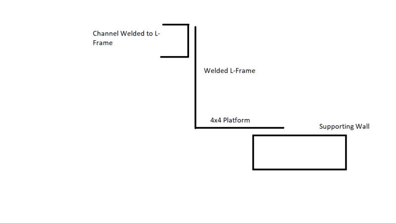
I am analyzing the supports for a small access platform (4x4). Maybe two workers on it at the same time with some equipment so max load is say ~ 2 kips.
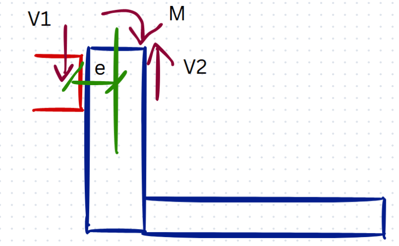
The platform is supported by a welded L-frame and a wall. There are two of those frames per each platform.
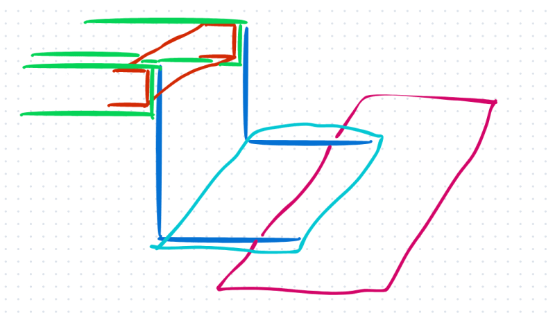
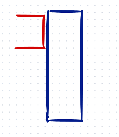
The channel is welded to the frame and the channel spans between two WF beams and is connected to the WF beams with a clip angle.
I'm trying to determine the best way to look at the torsion in the channel.
Worst-case scenario I would just point a point load at the middle of the platform and take the moment at the face of the channel as the torsion demand.
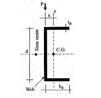
I can resolve the torsion force using the simplified equivalent tee method as per AISC DG9 and check the channel flange for weak axis bending, but I'm wondering what will happen at the connection to the W8 beam.
The clip angle is flexible and will rotate which should result in no torsion transmitted to the W8.
Anything else I should be concerned about regarding the connection or the channel?
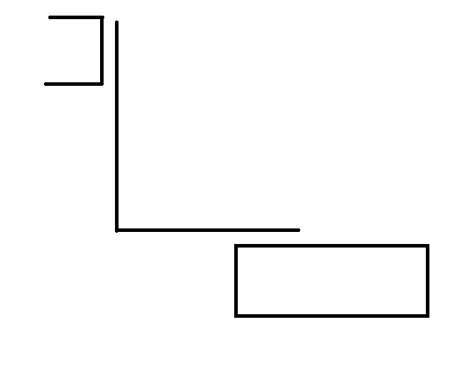
Sketch1_malwnh.png
 
Replies continue below

Recommended for you

Unfortunately, the geometry makes it difficult to find another support for the platform.
The workers have to come from up and then down onto the platform.

I added some markups to the sketch.

Sketch2_qpyhfo.png
 
A 3D isometric sketch would probably help a lot to understand the load paths and connections.

Isn’t there an applicable code that specifies the required load on the platform?
 
ASCE 7 specifies 40 PSF for catwalks which is what this platform acts as but I'd rather check it for a higher point load just in case.

The WF beams (green) support an existing work area.
The channel (red) spans between the WF beams (green) and is welded to a built-up L-Frame (blue).
The L-Frame (blue) supports one end of the new 4x4 access platform with grating and the other end sits on an existing wall (red).

Sketch3_smptti.png
 
Isn't it stable without torsion, if it is supported on the wall? If you're worried about accidental torsion, I wouldn't be based on that sketch, the alternate load paths are much stiffer.

I would go closer to 100 psf on this (or at least 65 psf), which I guess you are exceeding with 2kips total. Two guys with tools on a small platform will could be more than 40 psf already
 
Since there's a gap between the L-Frame and the wall the load will be shared between the frame and the wall. Wouldn't that portion of the load going to the L-Frame cause a torsional moment on the channel?
 
jreit said:
Since there's a gap between the L-Frame and the wall the load will be shared between the frame and the wall. Wouldn't that portion of the load going to the L-Frame cause a torsional moment on the channel?

Depends. It seems like the channel is being loaded pretty close to its shear centre. So minimal torsion.
 
The two L-frames are welded close to the center of the channel along its span.
So essentially, the moment arm for torsion will just be from the face of the channel to the shear center?

I analyzed the bottom horizontal leg of the L-Frame as a beam with a fixed end and a pinned end and was concerned the moment at the fixed end would be added to the torsion demand on the channel. For a 2 kip load, that's ~ 3x2x4/16 = 1.5 kip-ft.
Should that be added to the torsion demand or not? It's not that large but the Channel doesn't have a lot of torsional resistance so that's why I was concerned.

Sketch4_pgsoi5.png


Sketch5_k7trvj.png
 
Resolve that moment in the L frame not as torsion in the channel. The L frame should see some additional eccentric load from the distance from the shear centre of the channel to the center of the L frame hanger.
 
Why not connect the Lframe (blue) direct to the beams (green) and omit the channel (red)?

But even if you connect to the channel (red), the vertical legs of the Lframe (blue) will prevent torsion going into the channel (red).
 
So the shear in the channel is applied at the shear center with a moment arm to the center of the L-frame vertical leg. This causes a moment which should equal the moment demand on the L-frame. Since the shear is applied at the shear center, there is no torsion on the channel. As long as the channel is designed for the effects of that shear, the load path is valid.

A slightly larger vertical shear needs to be resisted by the L-frame due to e2 being smaller than e1.

Sketch6_xeuqkg.png
 
@BAretired the isometric sketch is a little rough.
The L-frame vertical legs are closer to the center of the channel and have rungs in between to act as a ladder for people coming up and down from the work area. So, the channel was used to span between the WF beams and the L-frame connects to that.
 
Status
Not open for further replies.
Back
Top