Continue to Site

Eng-Tips is the largest engineering community on the Internet

Intelligent Work Forums for Engineering Professionals

  • Congratulations KootK on being selected by the Eng-Tips community for having the most helpful posts in the forums last week. Way to Go!

accounting for thermal expansion in this shape 2

Status
Not open for further replies.

MartinLe

Civil/Environmental
Oct 12, 2012
394
There's decent formulas and rules of the thumb about for using 90° bends to absorb thermal expansion in pipelines.

How to account for this shape:
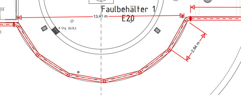
s_osrjno.png


The pipeline follows the parapet on the top of a series of vessels.

the pipe is stainless steel, DN 250, to the left it's ~7m to a fixed point (pipe runs through hole in ground) to the right it's ~16m to the next semicircle like the one in the picture. there are four more similar arches long the pipeline

I need to account for 1mm/m of thermal expansion.

I want to avoid expansion joints.

Surely at these obtuse angels these arches are not as good at absorbing expansion as a 90° bend with a long enough leg would be.

My first idea is to fix the middle of the arches and middle of the long segments, using 2D gliding supports in between (stainless steel supports on PTFE). what would be the peak stress in the pipeline due to thermal expansion?
 
Replies continue below

Recommended for you

Shouldn't be all that much of a problem. That's why you don't shoot arrows from a squared bow.

Try just guiding the straight pipe. Let the center of the bow slide laterally.

 
This could work too, probably better than my idea. What worries me is the bending in/near the 45° elbow.

the way I see it the distance that's approx. 13.41m in the drawing will be up to 15 mm shorter, while the circular part will be ~15mm longer. Now your comparison to the bow really makes sense!!!
Not sure how much stress this deformation would mean in my pipe and how to calculate.
 
The bending should be be low, because the axial force at the bow centerline will be small. You are "absorbing movement" in the 7m offset in the bow. That is roughly the same as an expansion loop without the elbows.

The only problem I see is fabricating the unusual curved shape of the pipe. Miter joints are usually not allowed on high pressure pipe. Better to hot bend, but expensive. So is making all those miter joints.

 
Marty,

What is your code of Record ? ASME B31.1 or B31.3 ? Something else ???

All have rules governing design and use of mitered piping bends. Not every all mitered configuration is acceptable ....

The piping codes will tell you that properly designed mitered bends often require increased wall thickness for pressure reinforcement

What is your wall thickness, design pressure, temperature and specific MOC ? More details equals better answers ...

Hopefully, the piping is at least Schedule 10S .... you are not designing with that Schedule 5S shit are you ?

I believe that your lateral expansion may be much greater than you believe, you may be surprised ...

Of course, your thermal expansion will "bow" outward from the center of the semicircle. Competently engineered pipe supports should be designed for this expansion in that particular direction

You want to use "rules of thumb" offered by strangers but this could be very accurately and completely evaluated using CAESAR-II in an afternoon.

You do not want to use expansion joints and I don't want to visit the dentist .....

Good Luck

MJCronin
Sr. Process Engineer
 
So the effective bend radius is about 10m?
If these are sch10 there is no reason not to cold bend them.
Even for 250 this isn't that tight of a bend to worry about.
I would be tempted to think about the fixed points as midway along each straight section.
This lets the radius section move inward/outward also.
Shouldn't be too difficult for good software to solve.

= = = = = = = = = = = = = = = = = = = =
P.E. Metallurgy, consulting work welcomed
 
Code is EN 13480 (which I don't have available)
to my best knowledge, miter joints at least up to 22.5° are allowed.

Wall thickness 5mm, design pressure 10 bar (testing pressure), temperature 40°C

I calculated axial expansion from -20°C to 40°C at 0.96 mm/m

The comment re. CAESAR-II is noted and probably correct. Just nothing I can do about right now. I'm not wiling to discuss office politics or our relationship to our client and likely contractors here.

ETA: I measured the radius bending of the arch, 7m

 
I was thinking it was half the 13.41m, but rightm it could be 10m. Even so that could be borderline for a cold bend.

MJC don't get excited. He just wants a bit of configuration advice.
Isn't it past time for the little white one?
 
Not a pipe guy, but I would not fix it near the ends of the semi-circle and would allow it to expand radially.

Rather than think climate change and the corona virus as science, think of it as the wrath of God. Feel any better?

-Dik


Dear Martin,

- Suggest you make available the subject code EN 13480 Part 3: Design and calculation..

- the code allows single miter joints less than 22.5° and more than 22.5° also.. but the allowable internal pressure formula changes..

If the single mitre bend with an angle θ not greater than 22,5 ° , the maximum allowable internal pressure, pa, is calculated in accordance with 6.3.4.

If the single mitre bend with an angle θ is greater than 22,5 ° , the maximum allowable internal pressure, pa, shall
be calculated from equation (6.3.5-1),( which is more stringent )..

I am not sure for that i got the full picture but i would prefer fixed supports at middle of the arches, sliding supports at the mid of the straight portions , and sliding supports at both directions at 75 degr. bends..

You may post the full piping sketch together with more data , to get better responds..

Good luck..
 
Why put fixed supports at the place that is the hardest to anchor and the best to allow flex? It is already the most flexible point. One does not often put guides and anchors in the middle of an expansion loop. Anchors and fixed supports are better placed in the middle of straight runs to force growth towards loops. Every time one places a guide or restraint of any kind, a pipe stress fairy loses her wings and stresses increase. The idea is generally to use the minimum number possible.

 
1503-44
It is 13.4m across, but that isn't a semi-circle. I estimated the size of the actual radius.
And thanks for saying that about anchors clearer than I did.

= = = = = = = = = = = = = = = = = = = =
P.E. Metallurgy, consulting work welcomed
 
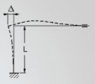
Peng & Peng give this formula for the required elbow length (for steel): L = 66*sqrt(D*delta) with Elbow length (that absorbs the elongation by bending) L, Pipe diameter D and elongation delta. All this assumes a 90° bend.

The offset between the outermost part of the arch and the straight run is 4,86 m

If I put fixed supports in the middle of the straight run, 9 mm elongation => 3.2m
At some places situations I'm forced to put the fixed support at the end of straight run (because of branching pipes) => 18 mm elongation => 4.6 m

The formula I use above doesn't really apply, because of the different angles. But it seems to indicate that at least the long elongation cannot be absorbed by the arches => compensators are required.

Is my thinking logical?
 

What do you mean by 9 mm elongation => 3.2m
18 mm elongation => 4.6 m

I do not understand.

 
Often small angle bends create bigger stresses than larger ones.

This one is a bit tricky as you have the 45 degree followed by the multiple 10-15 degree mitres or elbows?.

i generally agree with mr 44 - guide the straight bits and bend the bendy bit a bit more.

But working out stresses without ceasar or something similar??

Far from easy.

The bending on those flanges either side of the bow will also be problematic.

what's your neutral temp of installation? You only need to think about min and max temp from that neutral point. you seem to be taking 60 degrees of expansion - though I might be mistaken.

Remember - More details = better answers
Also: If you get a response it's polite to respond to it.
 
@1503-44 I mean the length of a 90° elbow required to absorb the elongation

@littleInch
10-15° elbows

Good point re. temperature - I'm thinking -20 (coldest winter plus failure of trace heating) to +40°C (operating temp.), installation will happen at 10-20°C or so.
 
Elbows don't absorb anything.

A "--> U <--" bend or "expansion loop" absorbs elongation by flexing as the loose ends, as the elbows, are pushed together. Elbows are relatively rigid when compared to pipe. It is the pipe that bends, not the elbows, hence stress at elbows are increased. Basically you assume that the elbows do not bend at all and all displacement is being accommodated by a pipe's ends moving relative to each other, bending the pipe, to meet the new elbow positions. A 90°Elbow remains at 90°.

That's why LittleInch says a small angle elbow makes things worse. All you do is misaligned the pipe, create eccentric axial load that get concentrated at the most rigid component. It's the entire loop with all its offsets and pipe lengths that adds flexibility and accepts movement by trading axial stress for bending stress. Axial stiffness of pipe is large, hence large axial stresses.
Bending stiffness of pipe is small = large displacements and little stress.
 
I was imprecise with my use of the term elbow.

Should have used this sketch:
not_elbow_aohsxo.png


As for the rest I understand and agree.
 
OK. That's the idea.

If you are operating and the trace heating fails, will it cause a shut down? If you remain operating, your pipe temperature will probably not drop to -20. If your pipe drops to -20, you will probably not be operating for long, so I think that operating pressure at -20 is not a valid design concern. Check operating pressure with thermal from +20 to 40 and again for non-operating 0 pressure from +20 to -20.

 
Status
Not open for further replies.

Part and Inventory Search

Sponsor