Eng-Tips is the largest engineering community on the Internet

Intelligent Work Forums for Engineering Professionals

  • Congratulations waross on being selected by the Eng-Tips community for having the most helpful posts in the forums last week. Way to Go!

ACI 17.5.2.1 Tension Reinforcement

Status
Not open for further replies.

BH6

Structural
Jul 31, 2020
33
US
Hi,
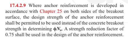
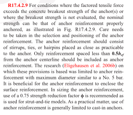
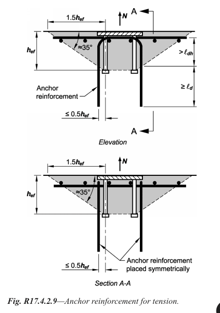
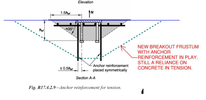
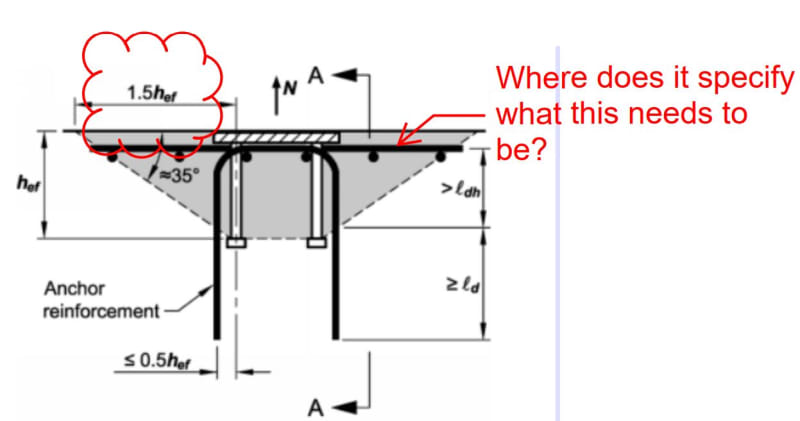
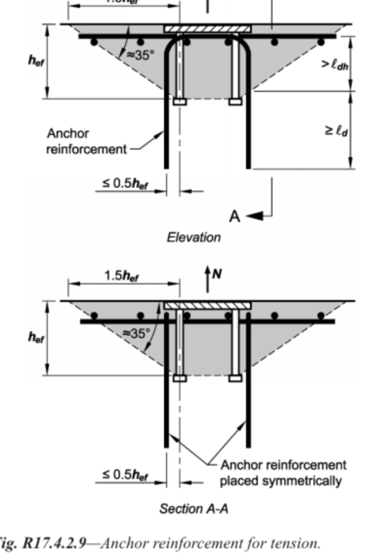
I am looking at the concrete pedestal reinforcement in seismic zone D for uplift on a column base plate. The commentary on ACI 17.5.2.1 states that research for allowing you to use the design strength of the anchor reinforcement instead of designing for concrete breakout strength was based on was or limited to anchor reinforcement with a maximum diameter of a #5 bar. Can you use something larger than a #5 bar as long as you meet the requirements in chapter 25 or is it better to keep the tension bars (I will be using U shaped bars) at #5 and then add more bars? I would need around (10) #5 bars instead of (5) #7 bars when using option D (17.10.5.3) and applying the overstrength factor to Eh. If I understand correctly all 10 bars would have to be within the .5hf (which would be 9" in my case for anchor bolts with 18" embed.) I also have a shear lug so placement of the reinforcement might get difficult. The pedestal is 24"X48" and it is 4' to 7' tall depending on the location in the wall.

Thanks for any thoughts or help in understanding this.
 
Replies continue below

Recommended for you

My understanding of tension reinforcement in this situation is that you have three paths available:

1) Anchorage per ACI 17.5.2.1. If this is your path then I do feel that you should stick with the #5 bars to be consistent with testing. I consider this path to be "Enhanced Anchorage" rather than true reinforced concrete design. Obviously, extending supplemental reinforcing beyond the failure frustum only engages a bigger failure frustum, it doesn't guarantee a complete load path to ground.

2) AISC's version of anchorage as described in their Design Guide 1 - Base Plate and Anchor Rod Design. Follow their limits as described in the design guide if taking this path.

3) Abandon ACI anchorage in favor of something more resembling true reinforced concrete design principles. The paper on this by Widianto is an exemplary resource: Link. Use whatever size reinforcing you like so long as the math checks out.

For something on a larger scale, as your problem seems to be, I would favor the second and third paths.
 
The code refs seem to be slightly different from my copy of ACI 318-14, maybe you're using ACI318-19, but it appears to me you are asking about tension anchor reinforcement specifically, not shear anchor reinforcement.

Two issues I see are first, you are explicitly using a larger size bar than is validated by research per the code commentary. I don't think this is a deal breaker, as it is stated in the code in the commentary, it is more of a recommendation/note to the user. However, you may not want to get too far away in size as a precaution.

Issue number two, once you increase beyond a #5 bar, the development length needed (ldh for your U-Bar) can cause excessive anchorage embedment requirements since you need to develop the anchor reinforcement above the assumed failure plane at the anchor head/welded nut. This may not be an issue for you since your pedestal sounds like it will be quite tall.

Taking a quick look at the paper KootK linked, the STM methods described there seem to address shear anchor reinforcement more than the tension anchor reinforcement, which seems to follow the ACI318 guidelines.

It also specifically says the following: "In order to limit the embedment depth of the anchor, a larger number of smaller-size reinforcing bars is preferred over fewer, larger-size reinforcing bars" and "Reduction in the development length cannot be applied in the areas of moderate and high seismic risk".

If it were me, I'd try to make #5s work with the layout you need for your shear lug, or maybe bump to #6s if needed.
 
Okay, thanks--
KootK said:
For something on a larger scale, as your problem seems to be, I would favor the second and third paths.

If you use option 2 or 3 would you still need to use the amplified seismic load? I guess I am a little confused on what is allowed when you hit the higher seismic zones and what still applies from ACI when using these other options.

KootK said:
1) Anchorage per ACI 17.5.2.1. If this is your path then I do feel that you should stick with the #5 bars to be consistent with testing. I consider this path to be "Enhanced Anchorage" rather than true reinforced concrete design. Obviously, extending supplemental reinforcing beyond the failure frustum only engages a bigger failure frustum, it doesn't guarantee a complete load path to ground.

Also, so I understand option 1. I thought the #5 bars would have to be taken down into the footing and developed into the footing which in this case makes for a lot of steel bars in a tall pedestal. But wouldn't that guarantee a complete load path? And by adding the "Enhanced anchorage" isn't that basically creating a strut and tie method?

 
This is the part of the Widianto paper that covers tension. I'd be looking at that as, effectively, a sort of non-contact lap splice similar to the second clip below.

strucbells said:
...more than the tension anchor reinforcement, which seems to follow the ACI318 guidelines.

To me, it appears similar to the guidelines in the AISC Design Guide 1 and not like anything present in ACI. Do you recall where you've seen similar treatment in ACI?

C01_ckkxgd.jpg


c02_asrflv.jpg
 
OP said:
If you use option 2 or 3 would you still need to use the amplified seismic load?

I would, yes, unless you're somehow able to demonstrate that you've got a ductile tension failure mode in the setup and are, therefore, able to use over strength capacity instead.

OIP said:
I thought the #5 bars would have to be taken down into the footing and developed into the footing which in this case makes for a lot of steel bars in a tall pedestal. But wouldn't that guarantee a complete load path?

A lot of designers would do that and, with the right attention to detail, it would create a complete load path. ACI, however, does not direct designers to do that. All they direct designers to do is develop the bars on either side of the anchor failure frustum.

This is a big part of what informs my preference to stick with #5 bars for path #1 when that path is strictly followed. Without specifying it explicitly, the method assumes that you're engaging a larger failure frustum than you would have had otherwise and that the tension delivered to that frustum can be resisted by it's expanded, unreinforced tension capacity. As such, I'm warry of massively increasing the density of reinforcing assumed to be "supplemental". Keep in mind that these provisions were developed for dinky little embed plates etc where the supplemental reinforcement was just a few $5 hairpins etc.

OP said:
And by adding the "Enhanced anchorage" isn't that basically creating a strut and tie method?

I would say no, it's not a strut and tie design until the details that make a strut and tie design compete are tended to. Extending the bars down to the footing may well be ONE of those details.
 
@OP: are we discussing a base connection on a braced frame here? Or a moment frame? I've been assuming the former.
 
KootK said:
@OP: are we discussing a base connection on a braced frame here? Or a moment frame? I've been assuming the former.

It is a braced frame. I do have a OMF as well but I haven't checked that yet. The OMF is assumed pinned at the base however.
 
ACI318-14 17.4.2.9 is very similar with slightly different values and cites a different paper:

11111_aeh56r.png


2222_dfhyro.png


33333_ebyu8y.png
 
strucbells said:
ACI318-14 17.4.2.9 is very similar with slightly different values and cites a different paper:

I suppose that it comes down to what one considers to be "similar". My understanding is that ACI318-14 17.4.2.9 is still, fundamentally, relying on the tensile strength of concrete for overall tension resistance. That, in contrast to Widianto and the AISC design guide which approach the problem as a non-contact lap splice after a fashion. That's what I've been viewing as the primary dissimilarity here.

C01_bkmye9.jpg
 
Interesting KootK...I don't see any reference in either ACI318-11 or 318-14 to that larger frustrum of breakout and concrete in tension when anchor reinforcement is provided. Do you have any publications you can share that describe that?

To me, the code states pretty clearly that you don't perform a frustrum check for breakout, but instead replace that with an anchor reinforcement check to be based on the yield strength of the rebar assuming it is developed above and below the failure plane, but using 0.75 instead of the usual 0.9 phi factor. So 0.75*fy*As.

That seems similar to a noncontact lap splice and similar to what Widianto describes.
 
strucbells said:
Do you have any publications you can share that describe that?

Only the book by Eligehausen that describes the underlying research etc.

strucbells said:
I don't see any reference in either ACI318-11 or 318-14 to that larger frustrum of breakout and concrete in tension when anchor reinforcement is provided.

Indeed. I would turn that around on you and ask if you see any reference in ACI indicating that the forces developed in the anchor reinforcement are to be passed to any specific place once developed? If not, what else would be the ultimate load resistance mechanism other than that expanded frustum?

strucbells said:
To me, the code states pretty clearly that you don't perform a frustrum check for breakout, but instead replace that with an anchor reinforcement check to be based on the yield strength of the rebar assuming it is developed above and below the failure plane, but using 0.75 instead of the usual 0.9 phi factor. So 0.75*fy*As.

I agree that, with the anchor reinforcement in play, you don't have to check the original, unreinforced frustum. But, then, where does the anchor reinforcement force wind up after it makes it's way into the larger mass of concrete?

To me, it seems that ACI leaves us to make one of two assumptions:

1) They are implying that the force developed in the anchor reinforcement is meant to be passed to other reinforcement via standard RC design principals, despite not explicitly saying that OR;

2) They are implying that the force developed in the anchor reinforcement is meant to be passed to another, usually much larger, concrete frustum in tension beyond the originally assumed failure plane.

My feeling is that #2 is ACI's intent.

C01_rzddjm.jpg
 
A couple questions about Figure R17.4.2.9 I have can get the ld and ldh but it shows the breakout at 1.5hef My understanding is that I don't have to check that or meet 1.5hef because I am replacing that requirement with an anchor reinforcement check. Am I reading that correctly? See attached picture


Also, I am using the shear lug to take the shear force. I will include ties but ACI 17 doesn't state that I necessarily need to. Is it good practice to include the ties anyway?
 
 https://files.engineering.com/getfile.aspx?folder=c0786eff-2161-45fe-8be0-0061bc5edfe9&file=Picture.pdf
I've gone with option #1..it may depend on the geometry/loads at hand. Working mostly on WWTP/WTP I have so far come across the need to detail tension anchor reinforcement for small to medium loads transferred to primarily vertical skinnier concrete elements (walls, pilasters, etc.) with plenty of nearby longitudinal reinforcing that is doweled into a foundation below that it isn't too difficult to lap to and provides a continuous load path.

I could see how if you had large tension forces transferred directly to a mat slab or other primarily horizontal element, you would go with Option #2.
 
OP said:
A couple questions about Figure R17.4.2.9 I have can get the ld and ldh but it shows the breakout at 1.5hef My understanding is that I don't have to check that or meet 1.5hef because I am replacing that requirement with an anchor reinforcement check. Am I reading that correctly? See attached picture

I believe they are showing the concrete breakout failure surface in that image to illustrate the development length requirement above and below the failure plane when you use anchor reinforcement. So, no, you would not need 1.5 hef minimum width, however, you will want to sketch out that projected failure plane to determine if you have adequate ldh above the intersection point when you are laying out your anchor reinforcement.


OP said:
Also, I am using the shear lug to take the shear force. I will include ties but ACI 17 doesn't state that I necessarily need to. Is it good practice to include the ties anyway?
Think about your load path, adding the shear lug removes the shear from the anchors, but you still need to check your concrete breakout based on the breakout frustum of your shear lug in the concrete. If you can't meet the breakout strength requirement, you'd need to provide ties and size them as needed. Can't hurt to provide them as long as there aren't clearance/install issues. Nice peace of mind for a few small diameter ties.

If you google "shear lug breakout strength" there are some examples out there on the internet. I believe ACI 318-19 added explicit shear lug design requirements and I think AISC DG1 talks about it as well. Not sure if they are aligned.
 
@strucbells: this is the kind of stuff that you see in the Eligehausen book. While a quick skim hasn't yielded anything that quite says what I'd like it to straight out, I feel that the highlighted bit below suggests an interpretation similar to mine. If the tension reinforcement could be replaced by longer anchors reaching back the same distance, it seem likely to me that we're talking about the same presumed failure mechanism, just pushed deeper into the body of the substrate.

C01_mrklz7.jpg
 
Thanks--

Strucbells said:
I believe they are showing the concrete breakout failure surface in that image to illustrate the development length requirement above and below the failure plane when you use anchor reinforcement. So, no, you would not need 1.5 hef minimum width, however, you will want to sketch out that projected failure plane to determine if you have adequate ldh above the intersection point when you are laying out your anchor reinforcement.

Thanks- just wanted to make sure I wasn't missing something.

strucbells said:
Think about your load path, adding the shear lug removes the shear from the anchors, but you still need to check your concrete breakout based on the breakout frustum of your shear lug in the concrete. If you can't meet the breakout strength requirement, you'd need to provide ties and size them as needed. Can't hurt to provide them as long as there aren't clearance/install issues. Nice peace of mind for a few small diameter ties.

I don't need them but it seems like they should be there--I guess just for peace of mind.
 
OP said:
...I don't have to check that or meet 1.5hef because I am replacing that requirement with an anchor reinforcement check. Am I reading that correctly?

I agree with your and structbell's opinions that this becomes moot with the tension reinforcement in play other than as a guide to know if you've got enough room for development.

OP said:
Also, I am using the shear lug to take the shear force. I will include ties but ACI 17 doesn't state that I necessarily need to. Is it good practice to include the ties anyway?

In my opinion, it's mandatory once you've used reinforcement for the tension breakout. It makes no sense to me to assume that your frustum has broken out in tension and then go and assume uncracked concrete for your shear load path. That, even if the tension frustum would be quite different geometrically from your shear frustum.

With regard to the question that you asked in red below:

1) That rebar is nice to have, and it improves performance, but I don't believe it to be mandatory.

2) If you supply that reinforcement, I feel that its only function is to improve anchorage for the hairpins. As such, it probably only needs to extend 6db or so past the bar being developed. I don't feel that its length is actually a function of 1.5h_ef although, clearly, the diagram makes that a bit confused.

3) In your particular application, I would not have top steel running across the pier (other than the uppermost column tie set). It's unnecessary in my opinion and will result in needless congestion.

C01_c7wr1g.jpg
 
@Kootk and @strucbells Thanks for your help understanding this!
 
@Kootk and @strucbells , stupid questions...

1. With the 2 U bars shown below on ACI, would that count as 4x Astxfy or 2x Ast x fy for tension capacity?
2. Can I just provide sufficient tension reo on one side of the failure plane (not both sides symmetrically).
3. Instead of U bars, can we use straight bars in the top matt (perpendicular to bolts) that are developed beyond the failure zone. The load I assume would be N*/Tan35

Thanks,
Screen_Shot_2021-07-17_at_1.00.24_PM_fujhif.png
 
Status
Not open for further replies.

Part and Inventory Search

Sponsor

Back
Top