Continue to Site

Eng-Tips is the largest engineering community on the Internet

Intelligent Work Forums for Engineering Professionals

  • Congratulations KootK on being selected by the Eng-Tips community for having the most helpful posts in the forums last week. Way to Go!

Adams/car Road Numeric Series of Values ... where are they ? 1

Status
Not open for further replies.

behnam jafari

Automotive
Apr 24, 2019
47
hi

how can I find road numeric values so I can give it as a signal to a full car model in matlab or Simulink ???
 
Replies continue below

Recommended for you

As Greg previously say to you, these points are embedded in the road file (rdf, xml). When performing almost any test for a Full-Vehicle assembly, the "Road Data File" string is indicated as mandatory, therefore, it seems to me that there is no need to set them via MATLAB. Another thing is if you want to use some of your values instead of the suggested standard ones. For that you need to change the road file. Use a text editor for simple roads or Road Builder for more complex ones. I hope I understand you correctly.
 
sorry for asking the question twice …


but I had a reason , I need a set of values for the Z-Direction or Ground elevation value because I need to validate my Full-Car model that exist in Simulink and I want to do this via Adams …

I had no intention to set road data files in Adams via MATLAB ...

when I try to export those xml files to excel ( so I can export them to MATLAB later on ) , I can't find the elevation … in that matter I think CarSim is easier than Adams because it gives out the Ground elevation data values but the problem with CarSim , as you know , is that you can't fiddle with almost everything like Adams …


I know I have become a nuisance but the gist of what i have been saying is :

I need ground elevation values based on time so i can give it to MATLAB signal builder as a road file so i can validate my Simulink Full-Car model ...

i wanted to export these values with til_wheel_contact_patch (z component ) ... but i got some strange results , because i got a pulse instead of a sine wave that i had defined for my road ...

thanks again
 
"I need ground elevation values ​​based on time"
In this case, the coordinates from the road file will not give you anything. I mean those that are open with help with the Road Builder menu in the Road Points tab (Z coordinate). These are just specific static profile points. In motion, еheir height will vary differently depending on the speed of the car. I suppose for this you used Acar - to match height and time. Well, if current measures do not help you, try creating Run-Time Clearance in template. It shows the shortest distance between objects. In the settings, specify the Contact Solid and Road Graphics types.
Now, it seems, we are moving in the right direction ...
 
I went into the postprocessing and went to Tools>Clearance>Create


then I got this :


Capture_zmge91.png


and I chose the ones you said I guess …

is it right ? is itt what you said ? what should i do after this ?
 
No, it is not. I meant creating inside a template in Template Builder mode. But now I realized that this will not work either, since the height of the car parts will also be variable, so the clearance is almost constant. We need to look for other ways to go from the a depence "height-length" to "height-time".
 
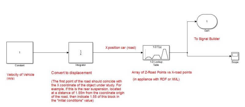
Maybe such a scheme in Мatlab will help you achieve what you want.
Scheme_huaow1.jpg
 
so what do I have to do?

does this mean that i should link adams and MATLAB for getting the height of the ground elevation for the road file ????


is this really going to be that hard ?


i thought that this is only a matter of getting road data from an adams file spreadsheet or something ? ( i mean from the post processor )


isn't there a way to get the road data file from postprocessor ??? how does a simulink code like this would help me get road data from Adams/car ????
 
this works too but can't adams give out road data file itself ????
 
Can you post the name of your road xml file here? or ideally the whole thing. Normally the xml is just a container that points to a text file (typically .rdf) that has a very obvious structure.


Cheers

Greg Locock


New here? Try reading these, they might help FAQ731-376
 
hi Greglocock

sorry for replying so late … thanks for getting into it

the name of the xml file is :

3d_road_obstacle_sine


when I open the xml file the other coordinates ( other than x direction ) are zero 0 . so they don't change …


how is it possible in a sine wave obstacle … when I know for a fact that I have added a sine obstacle to my road with certain aspects and I can see that in the results ...
 
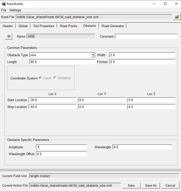
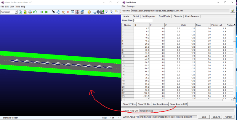
The Road Points tab contains points for an unobstructed road. Obstacle type formation is carried out in the Obstacle tab. For example:
312312312312_czfsxt.jpg

1212112w12_ia0ady.png
 
Status
Not open for further replies.

Part and Inventory Search

Sponsor