Continue to Site

Eng-Tips is the largest engineering community on the Internet

Intelligent Work Forums for Engineering Professionals

  • Congratulations SSS148 on being selected by the Eng-Tips community for having the most helpful posts in the forums last week. Way to Go!

adding a fence on high thin RC wall 4

Status
Not open for further replies.

gmd255

Structural
Apr 17, 2017
49
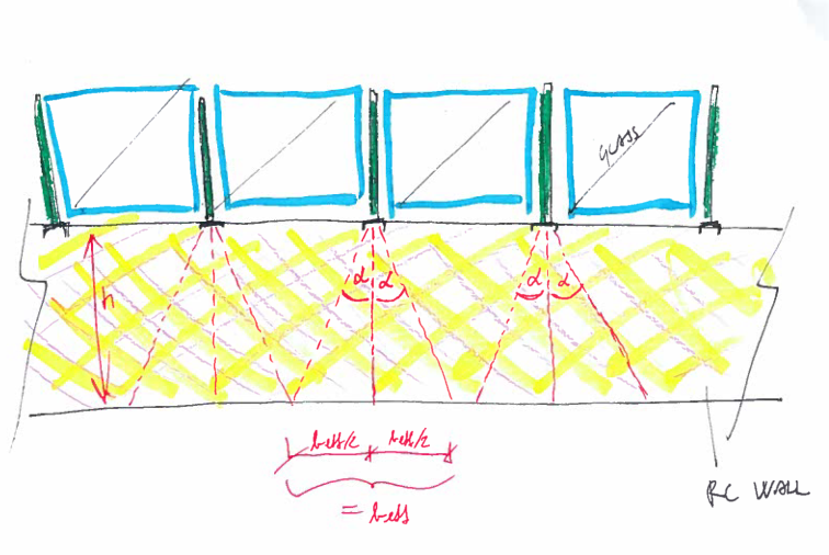
Im adding a glass fence on existing RC wall. Wall is thin (150 mm wide and 1580 mm high). Reinforcement in wall is fi8/20 cm. Since Im adding a fence on top, wall will be exposed to additional load from wind forces. So I have to check existing reinforcement (larger moments at the base of the wall).

My question is:
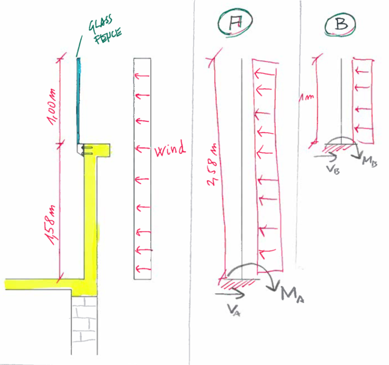
Can i consider a fence as an extension of existing wall when making a model (model A in the picture – cantilever with height of 2,58 m = 1,58 m wall + 1m fence)
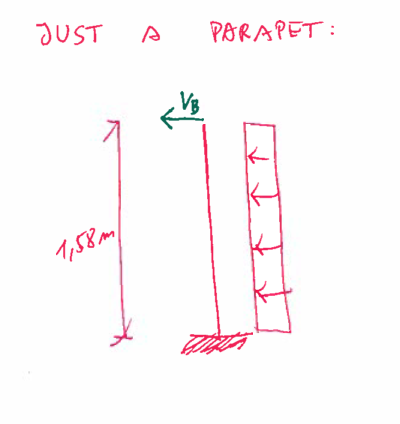
Or should I model wall and fence seperatelly (model B) and then add reaction from fence on the top of a wall where fence will be fixed.

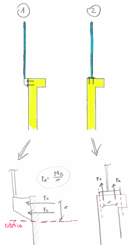
Im asking this because I dont know how to take into account tension forces (F1 and F2) from bending moment of a fence (detail 1). Does this mean that actual force on top of a wall is more like VB + F1?
If I fix fence on top of a wall as shown in detail 2 i dont have this problem?

Im confused since I get different results in both cases. In model B existing reinforcement is not sufficient but in model A it is.

1_hte6bl.png


2_q3g79n.png


3_afxgct.png
 
Replies continue below

Recommended for you

I would expect the same results in either case.
In your sketch A, I think analysis is straight forward.
In your sketch B, total moment will be equal to the moment from the wind against the wall + the horizontal reaction * the height of the wall + the moment at the base of the glass. Did you miss one of these components?

F1 & F2 in your final sketch are the forces in the bolts that need to be considered to design that connection, but I wouldn't utilize them to determine wall design forces.
 
For checking the moment at the base of the wall, whether you break the analysis at the base of the fence or consider it continuous, the resolution into the wall should be the same. A seems easier to me, but B shouldn't be too much harder. Just make sure to include the lateral shear that transfers through F1 and F2 into the top of the wall as well as the moment.
 
I've always used Case A. Ultimately, the wind is bending the screen and the wall simultaneously.
 
I'd normally run with section B because it resolves moments and shears for both the railing design and the wall design. To me, it's easier. Added: You need the forces to design the attachment.

Attachment 1 and 2:
Likely attachment 1 is easiest to develop forces, but, is more difficult to install. Attachment 2 is easier, but it may be more difficult to anchor, given edge distances, etc.

Dik
 
The results at the base of wall are theoretically the same in either case. B just shows the free body diagram of the upper glass portion and you need these values to design the connection.

From your question, I think it's possible that you're adding the bolt tension force to the shear and this is what's causing your model B to have a different base moment than model A. The bolt tension shouldn't be added to the overall model; it's an internal force that is necessary for the elements of your structure to act with continuity.
 
If i understand correctly... in model B you are thinking about putting tension forces you get from fence anchors in addition with shear force from the fence acting at the top of a wall?

I dont think thats the right approach since you ll be getting much bigger moments at the base of the wall that way and they are no way the same when using model A. Bending moments at the base of the wall should NOT be in correlation with how fence is fixed in a parapet in my opinion. right engineers?

If you choose model B, i dont know how you ll be taking MB - moment at the base of the fence acting on top of a parapet into account to get bending moment at the base of the wall. Someone shall explain that to you.

 
Suppose a = fence height and b = wall height
h = a + b

Model A,
Ma = wh2/2

Model B,
Ma = wa2/2 +wab +wb2/2
= (w/2)(a2 + 2ab + b2)
= wh2/2

Same result for Models A and B


BA
 
thank you for answers. It makes sense now. I apprecite it.
 
One more question...
I need to determine effective width of a RC wall at the base (beff). I need this so I can control if existing reinforcement at the base is sufficient. What should be taken for ALPHA? I was thinking about 30o

gf_u7zk8h.png
 
As long as the height of the wall is greater than the height of the railing, I would treat the effective width as the width of the railing spacing. If the wall is going to fail because someone leans on the rail... you have other more serious problems.

Dik
 
Status
Not open for further replies.

Part and Inventory Search

Sponsor