Continue to Site

Eng-Tips is the largest engineering community on the Internet

Intelligent Work Forums for Engineering Professionals

  • Congratulations The Obturator on being selected by the Eng-Tips community for having the most helpful posts in the forums last week. Way to Go!

adding bucked voltage to supply

Status
Not open for further replies.

thekman

Electrical
Sep 3, 2009
90
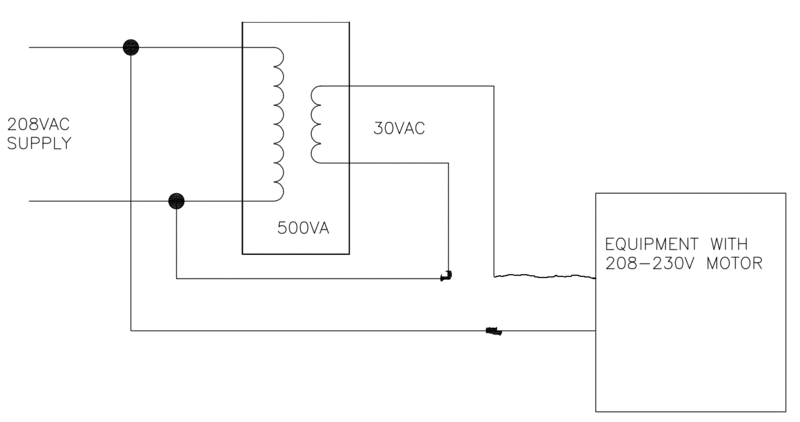
I was informed of an installation of a gate operator installation where the installers had run 10AWG wires a little over 1000' to supply a 208-230v singlephase motor. Due to the voltage drop, they installed 500VA buck transformers at the operators to get 30v or so and ran the transformer output in parallel with the supply wires, adding the voltage, compensating for the drop when the motor needed current. Is this a common practice? Is it a good or bad idea? Apparently it was more cost effective than using larger wires.
 
Replies continue below

Recommended for you

Something doesn't sound right. First off, "Buck" means Drop, more likely they are Boosting. And parallel? That's odd. Maybe you are just interpreting it that way? The buck/boost transformer is likely an auto transformer and to the untrained eye might appear to be a parallel connection, but electrically, it's more of a series/parallel connection.

And yes, that's a valid solution, weighed against the cost of wire. If the wire was already installed, you add the cost of removing and re-pulling, so it usually ends up less expensive of a fix. It would probably have cost less to use the correct size wire in the first place however.


"You measure the size of the accomplishment by the obstacles you had to overcome to reach your goals" -- Booker T. Washington
 
Yes, they 'bucked' it from the 208v supply down to 30v and "added" it to the same supply wires going to the transformer primary. Attached is how it was explained to me. The polarity may be switched concerning the transformer secondary, but you get the idea.
 
 http://files.engineering.com/getfile.aspx?folder=745954b2-c346-4e45-8b6d-ab8a87311c57&file=TRANSFORMER_ADDITION.pdf
thekman,
Could you please mark the primary & secondary polarity marks of the transformer and kindly re-upload?
 
It works very well. Have used that to boost (yes, that is the correct word) a weak grid from a mere 350 V to 400 V in order to make a kiln for ceramic pots work well. The transformer that takes voltage down to 30 V (in your case) is not a "buck" transformer - it is just a transformer.

Gunnar Englund
--------------------------------------
Half full - Half empty? I don't mind. It's what in it that counts.
 
There's too many connections. I imagine that it's connected in a boost auto transformer connection to send 240 (208+32) to the load.
 
Sorry, I don't have any more detail concerning the wiring or the transformer, etc...The drawing shows all the information I have been given for the way it was wired, what was used and how it was explained to me. I'm wondering if the information i got was incomplete or inaccurate.
I have no experience with an autotransformer, but am vaguely familiar with the concept. Sounds like that is what one is used for, boosting the voltage...It was explained to me such that the installers 'made up' for the voltage drop by adding it back with the low voltage output of the added transformer.


It is NOT an auto transformer. It is a normal transformer that adds voltage to the existing grid voltage.

Gunnar Englund
--------------------------------------
Half full - Half empty? I don't mind. It's what in it that counts.
 
The wiring diagram cannot be correct. It shows the primary and the secondary of the transformer wired in parallel, which would burn-up the transformer. The secondary needs to be wired in series with the load, and with the correct polarity. One polarity will add voltage and the other will subtract voltage. When wired this way I would call it an autotransformer or a buck/boost transformer.
 
Badly drawn, or perhaps clearly drawn but electrically incorrect.
 
My understanding of the terminology is;
1 Transformer connected as an auto transformer.
2 There are three common connections of a voltage adjusting auto transformer;
a Step up auto transformer (boost)
b Step down auto transformer
c Step up with the secondary connections reversed to drop the voltage instead of increasing it (buck and not really an auto transformer connection)
With primary and secondary voltages of 100 volts and 10 Volts and 100 Volts applied;
The step down connection will give 90.91 Volts.
The buck connection will give 90 Volts.

The connections shown will result in rapid transformer burnout.
Look at the connections of the 30 Volt secondary winding.
Both connections of the secondary should be to either the upper line to the load or to the lower line to the load, and the jumper between the two connection points must be removed. Then, depending on the polarity, the connection will either add or subtract 30 Volts from the load voltage.
This type of voltage boost varies with the load. It is not allowed under NEC as the feeder voltage drop is more than 3%.
It will serve for fixed loads. It is not good for varying loads.
A better arrangement is to transform the voltage up to 480 Volts or 600 Volts, size the wire for the allowable voltage drop and then transform the voltage back down at the load.


Bill
--------------------
"Why not the best?"
Jimmy Carter
 
Thekman this is what they did:

BoostTransformer_y0gclb.gif


Keith Cress
kcress -
 
Right on Keith. (Prepare for a visit from the over unity enforcers!! grin)

Bill
--------------------
"Why not the best?"
Jimmy Carter
 
Clever arrangement. Is the transformer big enough at 500VA? Wouldn't the transformer need to carry the full power to the load?
 
It is merely a two-winding transformer connected as an autotransformer. The 500 VA transformer is able to carry (208/30)*500 VA.
 

I get a slightly different connection than Keith. Connect windings in series so that polarity connects to non-polarity in order to step up.

Note that full load current passes through the secondary winding, but the voltage across that winding is not the load voltage. Therefore transformer VA doesn't need to match load VA.
 
stevenal,
The reduced voltage across the secondary tripped me up. I saw all the current going through the 2nd and jumped to conclusion.
Thanks, John
 
Status
Not open for further replies.

Part and Inventory Search

Sponsor