Continue to Site

Eng-Tips is the largest engineering community on the Internet

Intelligent Work Forums for Engineering Professionals

  • Congratulations The Obturator on being selected by the Eng-Tips community for having the most helpful posts in the forums last week. Way to Go!

adding bucked voltage to supply

Status
Not open for further replies.

thekman

Electrical
Sep 3, 2009
90
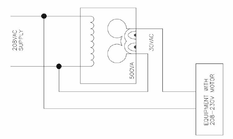
I was informed of an installation of a gate operator installation where the installers had run 10AWG wires a little over 1000' to supply a 208-230v singlephase motor. Due to the voltage drop, they installed 500VA buck transformers at the operators to get 30v or so and ran the transformer output in parallel with the supply wires, adding the voltage, compensating for the drop when the motor needed current. Is this a common practice? Is it a good or bad idea? Apparently it was more cost effective than using larger wires.
 
Replies continue below

Recommended for you

Of course stevenal's additional details are important ones. That's preventing anti-coil disaster where all the smoke spews forth. Unfortunately most transformers fail to show the 'dots'. I usually wire up the auto connection then check the resulting boost voltage with a meter before allowing any load to be applied. If the voltage is wonky(the smoking arrangement) from what is expected I swap the secondary leads and re-check.

Is there any dependable standard out there like H1 and X1 are always the dotted terminals?


Keith Cress
kcress -
 
TOTAL OUTPUT VOLTS x SECONDARY CURRENT (RATING) = The transformer's auto-connection capacity
The Secondary Current Rating is the transformer's non-auto rating, 500VA divided by the the secondary voltage 30V.

i.e.
LionelHutz said:
Isn't it 238/30*500VA?

238/30*500VA = 3,967VA is correct.

Of course in this mickey-mouse application described by the OP we don't actually know what the Total voltage is...

Here's a question:
In this application which end of the 10AWG run would be the better place to locate the auto-transformer?

Keith Cress
kcress -
 
There will be slightly more voltage at the load if the auto-transformer is at the source end rather than at the load end. Higher voltage means lower current and thus less voltage drop.
 
itsmoked said:
Is there any dependable standard out there like H1 and X1 are always the dotted terminals?

I think the standards are pretty dependable this way; H1/X1 indicates polarity. Transformers don't always match the standards, though. I have a mis-marked CT, one oddball out of a set of three, with strange secondary connections as a result.
 
Thanks stevenal, I'll wire that way first and it should then greatly improve the odds of not needing to re-wire.

I'm doing an auto-tranformer out of a 40VA transformer just today because the machine is a 230V machine and the motor brake is not releasing because the poor machine is being fed crappy 208V e.g. 203V and the brake demands 205V pulsating DC out of a bridge rectumfryer.

Keith Cress
kcress -
 
Haha, thanks, makes sense now. I went back and looked and realized the way I drew it couldn't possibly have been right. If I get any more info, like transformer pn, I'll pass along, thanks for the replies! I did a new version for Itsmoked... :)
 
 http://files.engineering.com/getfile.aspx?folder=c4e4ef5a-351a-4255-8e1a-3eded6dfe4a5&file=mickformer.pdf
URL]


ice_screenshot_20160113-145432_zbrki7.jpg


Indeed!

Keith Cress
kcress -
 
Status
Not open for further replies.

Part and Inventory Search

Sponsor