cycleback
Electrical
- Dec 15, 2017
- 5
I would appreciate some feedback on a compression die design that I am leading. My background is electrical engineering and I have never designed a die before. This is in an academic environment so there is little practical experience with this sort of thing. I have met with a tool and die maker but I still have a number of design questions that I am unsure about.
The intent of the die is to compress copper coils in prototype quantities (~20 units produced) under fairly high loads, ~300 to 400 tons. I am trying to design something that will work the first time because I don’t really have budget to make a second but it doesn’t need to be overly fancy since it is only for making very limited quantities.
The final compressed dimensions of the coil are ~5.23” x 2.26” x 1.09” with the compression surface being 4.84 in^2. The pressure on coil will be 61 kPSI - 165 kPSI.
An exploded view of the design as it currently stands follows:
Link
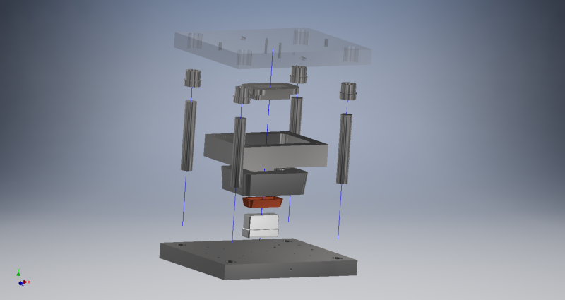
1) The design current uses a yoke, die, bobbin, and punch. The compressed coil is formed in the cavity created by the die, bobbin, and punch. The yoke surrounds the die to add strength as there are concerns that the die might crack given the pressures and forces. There is a taper on the outer die perimeter and the yoke inner perimeter for the yoke to contain the die as the coil tries to force it outward.
[ul]
[li]Does it make sense to use a yoke? Would the yoke be better replaced with just a larger die?[/li]
[/ul]
2) For the die, punch, and bobbin I have specified A2 tool steel hardened and tempered to best compromise of hardness and toughness. From the reading I have been doing about hardening A2 the best combination of hardness and toughness occurs with a tempering at ~204 Deg. C and results in a ~60/62 Rockwell C hardness. The yoke is currently specified with tempering at 350 Deg. C ~58/57 Rockwell to increase the strength at the expense of hardness.
[ul]
[li]Is this likely the correct steel to use? I need high hardness to avoid deforming the die and have the copper extrude between the die, bobbin, and punch but I am also concerned about the die cracking. I was also considering S7 steel.[/li]
[/ul]
[ul]
[li]Does this tempering temperature seem correct?[/li]
[/ul]
[ul]
[li]Do I need to specify anything further on the print in terms of hardening, tempering, quenching, etc.?[/li]
[/ul]
3) The tolerances between die, punch, and bobbin are a locational clearance fit H7/h6. I want to be able to put together and take apart the die, punch, and bobbin but also not have copper extrude between them under the high pressures.
[ul]
[li]Is this the correct/best tolerance to use?[/li]
[/ul]
4) The current design uses a die set which locates the die, yoke, punch, bobbin, relative to each other using one round and one diamond locating pin in each part. One bolt is then threaded into the die, yoke, and bobbin and two bolts in the punch.
[ul]
[li]Would it be better to have an additional diamond locating pin or an additional bolt?[/li]
[li]Should the diamond pin be located diagonally across from the round locating pin or collinear through the part?[/li]
[/ul]
5) Since I would like to be able to reuse the die set I have thought about using locating pins with a threaded shank and bolting them in with bolt countersunk into the bottom of the die set plate? The more permanent alternative is to press fit them in. The press fit probably gives better locational tolerance.
[ul]
[li]Any recommendation which type of locating pin to use? Press-fit or threaded shank?[/li]
[li]Is there any other source for threaded shank locating pins than Misumi?[/li]
[/ul]
6) The minimum thickness on each side of the die (2.22”) and yoke (1.5”) compared to the coil thickness (0.375”) of one side.
[ul]
[li]Do you think the die and yoke are thick enough? Is the die big enough? If I can make it smaller that would be great from a cost and handling perspective.[/li]
[/ul]
7) I read somewhere that the die set guide pins should be ¼” shorter than the shut height of the die. This seems counter-intuitive to me.
[ul]
[li]How long should the die set guide pins be above the top die plate when the die is fully closed?[/li]
[/ul]
8) Right now the die set is specified with short shoulder plain bushings.
[ul]
[li]Is there any disadvantage of using short should bushings? They give more flexibility for reusing the die set.[/li]
[/ul]
9) How is the surface or polishing typically specified on the print?
[ul]
[li]What surface or polishing level would you recommend?[/li]
[/ul]
10) In some of the books on die design that I have been reading they recommend hardened backup plates between 3/8” to ½” between the die and punch and the die set plates. For this application would they really be needed since so few parts are going to be produced?
11) Any idea of what you would estimate is a reasonable cost for this so I don’t get taken to the cleaners trying to get it made?
Any comments or feedback would be greatly appreciated.
The intent of the die is to compress copper coils in prototype quantities (~20 units produced) under fairly high loads, ~300 to 400 tons. I am trying to design something that will work the first time because I don’t really have budget to make a second but it doesn’t need to be overly fancy since it is only for making very limited quantities.
The final compressed dimensions of the coil are ~5.23” x 2.26” x 1.09” with the compression surface being 4.84 in^2. The pressure on coil will be 61 kPSI - 165 kPSI.
An exploded view of the design as it currently stands follows:
Link
1) The design current uses a yoke, die, bobbin, and punch. The compressed coil is formed in the cavity created by the die, bobbin, and punch. The yoke surrounds the die to add strength as there are concerns that the die might crack given the pressures and forces. There is a taper on the outer die perimeter and the yoke inner perimeter for the yoke to contain the die as the coil tries to force it outward.
[ul]
[li]Does it make sense to use a yoke? Would the yoke be better replaced with just a larger die?[/li]
[/ul]
2) For the die, punch, and bobbin I have specified A2 tool steel hardened and tempered to best compromise of hardness and toughness. From the reading I have been doing about hardening A2 the best combination of hardness and toughness occurs with a tempering at ~204 Deg. C and results in a ~60/62 Rockwell C hardness. The yoke is currently specified with tempering at 350 Deg. C ~58/57 Rockwell to increase the strength at the expense of hardness.
[ul]
[li]Is this likely the correct steel to use? I need high hardness to avoid deforming the die and have the copper extrude between the die, bobbin, and punch but I am also concerned about the die cracking. I was also considering S7 steel.[/li]
[/ul]
[ul]
[li]Does this tempering temperature seem correct?[/li]
[/ul]
[ul]
[li]Do I need to specify anything further on the print in terms of hardening, tempering, quenching, etc.?[/li]
[/ul]
3) The tolerances between die, punch, and bobbin are a locational clearance fit H7/h6. I want to be able to put together and take apart the die, punch, and bobbin but also not have copper extrude between them under the high pressures.
[ul]
[li]Is this the correct/best tolerance to use?[/li]
[/ul]
4) The current design uses a die set which locates the die, yoke, punch, bobbin, relative to each other using one round and one diamond locating pin in each part. One bolt is then threaded into the die, yoke, and bobbin and two bolts in the punch.
[ul]
[li]Would it be better to have an additional diamond locating pin or an additional bolt?[/li]
[li]Should the diamond pin be located diagonally across from the round locating pin or collinear through the part?[/li]
[/ul]
5) Since I would like to be able to reuse the die set I have thought about using locating pins with a threaded shank and bolting them in with bolt countersunk into the bottom of the die set plate? The more permanent alternative is to press fit them in. The press fit probably gives better locational tolerance.
[ul]
[li]Any recommendation which type of locating pin to use? Press-fit or threaded shank?[/li]
[li]Is there any other source for threaded shank locating pins than Misumi?[/li]
[/ul]
6) The minimum thickness on each side of the die (2.22”) and yoke (1.5”) compared to the coil thickness (0.375”) of one side.
[ul]
[li]Do you think the die and yoke are thick enough? Is the die big enough? If I can make it smaller that would be great from a cost and handling perspective.[/li]
[/ul]
7) I read somewhere that the die set guide pins should be ¼” shorter than the shut height of the die. This seems counter-intuitive to me.
[ul]
[li]How long should the die set guide pins be above the top die plate when the die is fully closed?[/li]
[/ul]
8) Right now the die set is specified with short shoulder plain bushings.
[ul]
[li]Is there any disadvantage of using short should bushings? They give more flexibility for reusing the die set.[/li]
[/ul]
9) How is the surface or polishing typically specified on the print?
[ul]
[li]What surface or polishing level would you recommend?[/li]
[/ul]
10) In some of the books on die design that I have been reading they recommend hardened backup plates between 3/8” to ½” between the die and punch and the die set plates. For this application would they really be needed since so few parts are going to be produced?
11) Any idea of what you would estimate is a reasonable cost for this so I don’t get taken to the cleaners trying to get it made?
Any comments or feedback would be greatly appreciated.