Flying Whale
Mechanical
- Dec 20, 2024
- 15
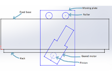
I have a geared motor bolted onto a moving plate supported by rollers standing on a fixed base. The same fixed base has a rack on the bottom. There are 4 rollers, 2 on each side of the fixed base, and they're on separate shafts (there's material between the two sides, and it cannot have holes). The moving plate assembly can get up to a mass of 1,000 kg.
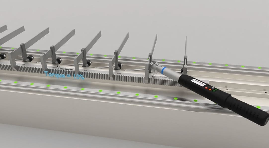
Sizes and materials here are quite large (plate is 600mm wide, made of 12mm laser-cut steel, and the fixed base is a standard beam profile) so no tolerances can be reliably specified to get the correct mesh engagement. This has been built and tested, it failed because the gear teeth didn't fully engage, then solved with a not-so-repeatable nor time-efficient method for a long-term product line. (Having to shim the rack to push it into the pinion is not a solution, at least for our requirements)
I've tried to find some existing designs where gears are designed with adjustable centers, but my research has led me nowhere. One idea I've had is to mount the rollers on shafts with offset centers (one of which is threaded and tightened to the plate by a nut), but that adds complexity to the assembly pretty quickly, since the four rollers have to be adjusted independently.
Any help is appreciated, thanks.


