Hello fellow engineers. I am working on a big structure that at some point will have a truss beam connecting in the web of other beam that is transversal to it. Since I am working with a 3d analysis I am a little confuse on how to model this situation on the software. I've attached 3 pictures to better explain.
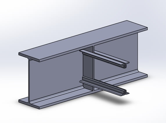
In picture one there is a 3d representation of what I am trying to design, the connection will be either bolted or welded, yet tbd.

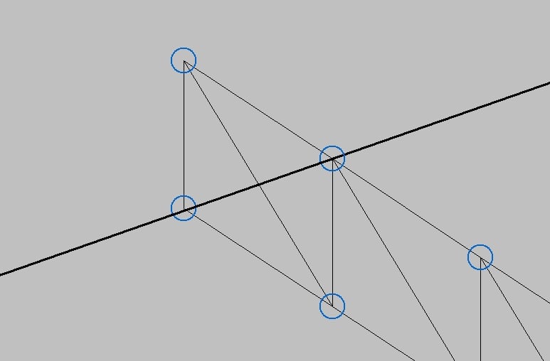
In picture two is my first idea of how to represent that in my software. I designed the truss as it was over the beam and put a compression member at the end that represents the plate i will be using to fix my truss.

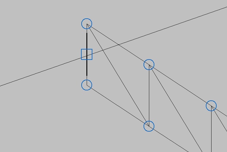
Picture three show another way I thougth though I am not so sure about it. I ve created a member that connects at middle both top and bottom chord to the beam.

What do you guys think about this, are any of those close to beeing a good representation of this situation or both are actualy wrong?
In picture one there is a 3d representation of what I am trying to design, the connection will be either bolted or welded, yet tbd.

In picture two is my first idea of how to represent that in my software. I designed the truss as it was over the beam and put a compression member at the end that represents the plate i will be using to fix my truss.

Picture three show another way I thougth though I am not so sure about it. I ve created a member that connects at middle both top and bottom chord to the beam.

What do you guys think about this, are any of those close to beeing a good representation of this situation or both are actualy wrong?
