Sparweb
Aerospace
- May 21, 2003
- 5,167
Working on a turboprop aircraft whose SRM defines aerodynamic smoothness in terms of maximum protrusion beyond the skin. It's tight enough that everyone says you can't have protruding head rivets. However, the purpose of the rivets is a doubler, and the doubler is a reinforcement to an antenna, and the antenna is a blade 16" long with a 10" chord. A big shark-fin blade that has plenty of drag. I am looking at the overall situation and considering whether the rivets really have to be flush for "aero smoothness" when the antenna will add many pounds of drag in the free air stream.
Other considerations:
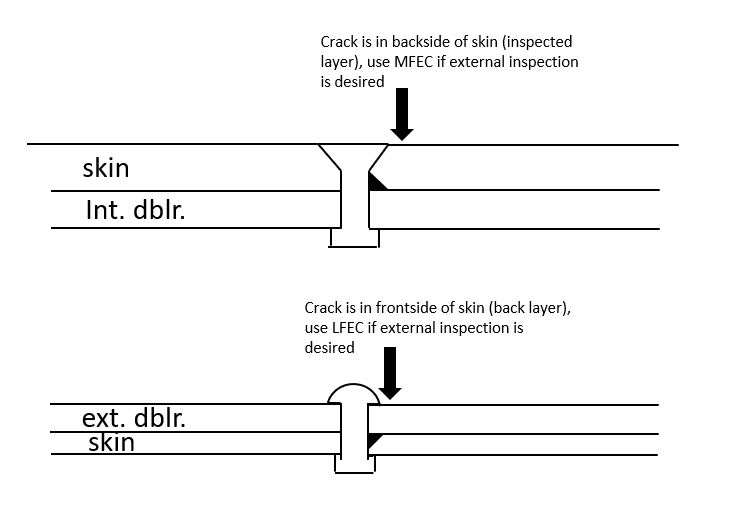
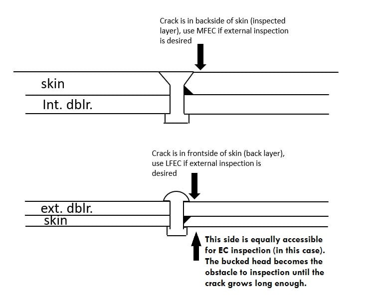
-Fracture mechanics of countersunk rivets is poor compared to protruding heads
-The skin is very thin, chem-milled. Even low-profile rivets (NAS1097) are knife-edge in 0.032 thick skin.
-Blade antenna is stabilized by rigid internal structure but that means there are out of plane loads on this doubler. Small, but not zero.
-Boundary layer thickness in the area is at least 1/4" (this is not a guess, I have experience with this)
I think I'm gearing up for fight but is there really one to be had?
If the purpose of the smoothness requirement in the SRM has more to do with blending edges of repairs, and overall fuel economy of the aircraft in service, and "nice to have" then could an argument for structural integrity beat it?
Other considerations:
-Fracture mechanics of countersunk rivets is poor compared to protruding heads
-The skin is very thin, chem-milled. Even low-profile rivets (NAS1097) are knife-edge in 0.032 thick skin.
-Blade antenna is stabilized by rigid internal structure but that means there are out of plane loads on this doubler. Small, but not zero.
-Boundary layer thickness in the area is at least 1/4" (this is not a guess, I have experience with this)
I think I'm gearing up for fight but is there really one to be had?
If the purpose of the smoothness requirement in the SRM has more to do with blending edges of repairs, and overall fuel economy of the aircraft in service, and "nice to have" then could an argument for structural integrity beat it?