Continue to Site

Eng-Tips is the largest engineering community on the Internet

Intelligent Work Forums for Engineering Professionals

  • Congratulations GregLocock on being selected by the Eng-Tips community for having the most helpful posts in the forums last week. Way to Go!

AGMA surface endurance strength and AGMA bending strength 6

Status
Not open for further replies.

noobita

Electrical
Oct 19, 2015
20
Does anyone knows how to calculate the AGMA surface endurance strength and the AGMA bending strength?

I'm looking for a general formula (if there is, the ones i know are for steel), if there is? If not, does anyone knows these values for aluminum 2024-t4 and 303 stainless steel ( i need these values to calculate the safety factors).

For example, Sf(safety factor for bending) = (St x Yn/ Kt x Kr)/sigma (at this moment i have all values less the St).
Best regards
 
Replies continue below

Recommended for you

The general formulas are in AGMA 2001 Fundamental Rating Factors and Calculation Methods for Involute Spur and Helical Gear Teeth.

AGMA reviews materials in multiple standards, including AGMA 2004 Gear Materials and Heat Treatment Manual. Neither aluminum alloys nor austenitic stainless steels are discussed beyond a single sentence saying that they are non-standard and require special analyses.

Your two specific alloys are going to be poor gear materials with respect to wear and resistance to contact stress.

Good luck with your analysis.
 
Thanks for your reply CoryPad. That was what i was seing, that's why i came to the forum to know if anyone knows this values.

About this materials being poor gear materials, they are not, it depends on your application. For example, sdp-si ( a big gear's manufacturer, uses 303 stainless steel and aluminum 2024-t4 (i'm trying to choose which gears to use, that's why i need this values).

Hope someone knows this values.

Best regards
 
Are you transmitting power or just motion? I don't think aluminum would be a good choice if you were transmitting power.
 
Both power and motion, but are small values (~0.03 hp). From matweb, they seem to have a yield and ultimate strength close to other steel metals (hardened ones). Also, it is in shingley's mechanical engineering design book has a good material for gears.

Best regards
 
As CoryPad noted, the AGMA gear design approach you are asking about that uses various factors is intended to be used with the material properties recommended by AGMA for this approach. There are other AGMA specs that provide every equation you will need to calculate the precise tooth bending and surface contact stresses of your gear design. You can find some fatigue properties for 2024-T4 aluminum in MIL-HDBK-5. But you probably won't find fatigue data for 303 cres, since its poor fracture characteristics make it unsuitable for structural applications.
 
Hi, tbuelna, just saw the MIL-HDBK-5 but i coulnd't find what i'm looking for (used ctrl+f and searched for 2024), only could found the ultimate and yield strength, not the allowable contact strength and allowable bending strength.

Best regards
 
Tooth bending is based on tensile stress in the root fillet area. For tooth bending you need to consider all of the factors you would with any fatigue analysis, such as load cycles, load conditions, surface finish, mechanical working of the material, fillet shape, etc.

Capture_gf0v6d.png
 
Thanks again tbuelna, but again, the values showned here are for the ultimate strength and yield strength. Maybe i didn't understood the values from the book. For example, (this will be kind of a newbie question) agma gives this equation, based on hardness, for grade 1 steel: <<Contact-fatigue strength number, Sac = 2.22HB + 200 MPa>> and <<Allowable bending stress number, Sat =0.533HB +88.3 MPa>>. St and Sc are used in the used in the bending factor of safety and wear factor of safety equations, respectavily, and are this values i'm looking for, or some sort of calculating them or estimating (both two sources you have posted talk about ultimate strength and yield strength.

Hope you could reply me.

Best regards

EDIT:

After reading the book again, i found that they have changed the designations of what i'm looking for, so title is wrong. What i'm looking for is the allowable stresses numbers (Sat, Sac). Does anyone know this values or a way of calculating them (sorry for confusion tbuelna, since you were always posting info about ultimate strength and yield, hope you can help me in this too :D)?


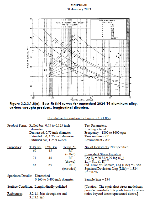
Rather than using the simplified AGMA design approach that uses various factors, you need to calculate the actual root fillet tensile stress due to tooth bending. You can find all the equations needed in the AGMA specs. For a fatigue case where there might be varying loads and frequencies, you need to establish a single composite load and number of cycles value to use. Take the root fillet tensile stress value you calculate and compare it to the appropriate curve in the chart above. If the gear tooth is subject to reversing bending loads (this is common with idler gears), make sure to take that into account when using the chart above.
 
Thanks tbuelna, i'll try to find that equation...Will reply as soon as i make the calculations.

Best regards

EDIT

After searching around, i couldn't find the equation, could you please point it to me or post it here (this was better if forum had private messages, since you are only one helping tbuelna)

Only could find/had these ones (i think that they are not the equation for the root fillet, this are for strength/stress):

bending
1
bending.png


2
bending1.png


contact stress
3
conatct.png


4
pitting2.png


Imagine this (what will be the first stage): 8W motor, 7000 rpm pinion, 13 teeth pinion, 41 teeth gear, 80 diametral pitch (0,3175 module), 0,1 inches face width (2,5 mm), designed for 10^8 cycles, SF > 1,3, sigmalim= 42.5 :

From equation 1, i can transmite a maximum of 60500 psi, and from Ft = (1.95*10^6*P)/dg*n (dg=working pitch diameter, n= rotational speed of pinion, P=power transmitted), Ft=800psi, so Ft<<Ftlim
Now from equation 2, Ft = 9527 psi, so, what is the correct value?

Best regards
 
noobita-

I would recommend reading thru AGMA 917-B97 for a step-by-step approach to designing a spur gear. Sections 6.9.5 & 5.6.1 discuss methods for determining tooth bending stress other than the AGMA geometry factor method you are using. Section 6.9.6 discusses contact stress. And sections 10.2 & 10.3 briefly discuss using 300 series cres and wrought aluminum alloys for gears.
 
Hi tbuelna, again, thanks for your reply, but again this file couldn't clear my doubts(it doesn't have the contact stress for 2024-t4). But from i read from the file, they say that gear designers are based in experience, this is, making the system and testing them, i think that i will try it (from my calculations, for the final stage, the gear will experience a contact stress of 200k psi and a bending stress of 44k psi, which material would you recomend - 4130 or 4340?).

Best regards
 
Here's a couple comments based on the description of your gear set provided above. First, it will require quite a bit of effort to produce an 80DP 13T pinion with the precision you seem to be looking for. Second, a hertzian contact stress of 200ksi at 10^8 load cycles is a bit too high. You should keep the contact stresses below around 175ksi for 10^8 cycles, and even then you'll need to use a case hardened alloy steel. For an 80DP gear tooth the most practical case hardening option is nitriding. I'd suggest using vacuum melt Nitralloy N (AMS 6475) or vacuum melt 4340 (AMS 6414). Bending stress of 44ksi at 10^8 cycles (unidirectional) is OK for either material. Third, due to the very small size gear teeth you are using it can be difficult to accurately predict tooth stresses due to the difficulty in controlling geometry errors when manufacturing such small gear teeth. So you need to be very conservative with your stress limits.
 
noobita

Can you be more specific for the gears are intended for?
Cycle number?
Etc.,

We have used such gears for specific application that include both for power and motion but for limited cycle numbers.
 
tbuelna first of all thanks for your reply, again. And sorry for the misunderstand, the system with 80DP is the first stage of gearbox, the one i talk in this last point is last stage (gearbox is composed by 5 stages), which has 48DP (and values presented for stresses are bidirectional values - 1/0.7 = 1.43 x value of unidirectional - hope i have used the right multiplying factor - this was what was stated in the book). The first stage has a bending stress of 10kpsi and contact stress of 40kpsi, so there is no problem there (for 4130/4340 or even astm no.50 there isn't any problem). Only problem is really last stage, which will withstand a higher value of force (last stage is 14 pinion teeth and 39 gear teeth).

israelkk, trying to reply to your questions, the gears are intented to use in a speed-reducer gearbox, in which the motor has 0.009 hp (approximately 7W, so this will be the transmitted power), the motor speed (pinion speed) is about 10600 rpm (no load speed - i'm using this value, but don't know if i should use another value, like max continuous speed, or even a lower value - because force will increase if speed reduces), and is intended to reduce speed to about 55 rpm (so, the ratio is about 193, for that i'm designing a 5 stage gearbox). Would you like that i post my preliminary design of the gearbox? Oh, and there is a space constraint, gears should fit in a space of 1x2 inches (25.4x50.8mm), height isn't a constraint, but should be less than 30mm.

Best regards

PS: i use SI system, but has i think this is an american forum, i'm posting the american units. If you prefer (and is better for me) i can only post in the SI system..
 
What is the maximum torque the gearbox outputs?
Is it rotate multiple rotations (continuous rotation) or just limited angular output against a torque load?
How many cycles the gearbox will see against the maximum torque?
If it is for limited angular output, how fast it needs to reach the maximum angle against the maximum torque?
 
So,the maximum torque that the gearbox will have to output will be 5.0Nm(approximately 780 oz-in). Multiple rotations, without limits. Against the maximum torque, since it must handle 10^8 cycles in maximum continous torque, it should handle at least 10^4 cycles at the stall torque (which is the 5Nm).

Would you like me to post the calculations that i already have with materials, etc, and each stage of the gearbox?

Thanks for your help and best regards (eng-tips doesn't have pm right?)

 
Remember, that to show that the system for sure will last 10^4 cycles at the stall torque you should prove by testing that it can live 10^5 cycles (factor of safety of 10 for fatigue analysis some will argue factor of safety of 4). Same apply for the maximum continuous torque, you need to show by tests between 4x10^8 to 10^9 cycle before failure. The criteria for failure should be established too. It may be a fracture of the gear tooth or position accuracy loss, depends on the application. I doubt that you can achieve those requirements in the space you defined using SDP-SI, PIC or BERG type gears. You probably need to use custom designed case hardened and grinded gears, if any.
 
Thanks for your answer israelkk, i was looking already for custom spur gear, the suppliear gave me the fallowing materials (the ones they use):

1) Carbon Steel
SC45 (1045)
40Cr

2) Alloy Steel
42CrMo (SAE 4140, SCM 440)
20CrNiMo (AISI 8620)
40CrNiMo (SAE 4340)
20CrMnTi (This is most used for spur gear and helical gear in China)

17CrNiMo6 or 18CrNiMo7 for spiral bevel gear

3) Aluminum
6061-T6 for some gears and timing pulley.

For now, my problem is really find the specific materials for each gear, so it can last all cycles

PS: This afternoon i will try to post an already made design which lasts highest torques that my gears are supposed to handle - hope this can help

EDIT

So, here is the details of the other gearbox:

(13/54) -> 80dp
(15/53) -> 80dp
(15/35) -> 64dp
(13/27) -> 48dp
(14/39) -> 48dp

Ratio is, approximately, 198. In this design, the maximum torque (stall torque) is 7.3 N.m, power transmitted 8W, and maximum continuous torque is 2N.m. Which material do you think is used in this gearbox? PS: this is a tested gearbox, data was taken from internet, don't know any other specs.

Best Regards
 
Status
Not open for further replies.

Part and Inventory Search

Sponsor