Eng-Tips is the largest engineering community on the Internet

Intelligent Work Forums for Engineering Professionals

Air Trap in the Suction of Condenser Pipe of Chiller

Status
Not open for further replies.

Wayne _ Lunar

Mechanical
Jul 10, 2023
9
0
0
VN
Hi all

I am the new member. I think this forum is very useful for an new engineer like me.

I have a question, please help to clarify for me.

We are conduct balancing for a chiller system. There are 3 Cooling tower but one CT, the suction pipe one of 3 CT has a one trap pipe as below:
Air_trap_y4x0l8.jpg


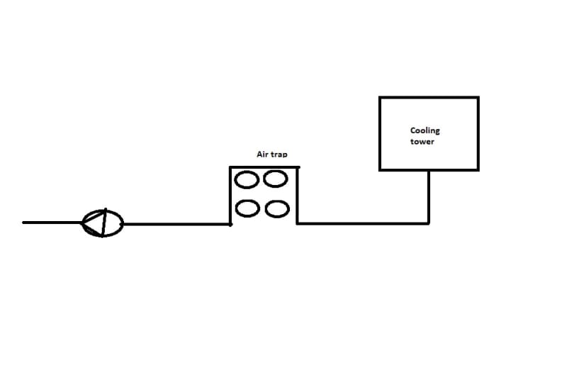
I have a question: Does the pipe arrangement like this cause any impact to the circulation of the Condensed pump? Air will trap inside the pipe or with a high water velocity, air will move out of the air trap part?

Thank you so much!
 
Replies continue below

Recommended for you

first, welcome but please don't use abbreviations, even when you think its a well known one - so CT?? Cathode Tube?

Difficult to say much on this without some dimensions, sizes, flow rates and velocities.

If you're doing >1m/sec you can essentially "blow" air out of any pipe system so long as you maintain positive pressure above atmospheric.

This is a syphon effect here and is definitely not ideal but if the base of the cooling tower pond is higher than the top of the high bit of the syphon plus the syphon itself is fairly low ( <5m) you might be ok.

but devil is in the detail here so gives us a more accurate drawing with data on it and we might get somewhere.

Remember - More details = better answers
Also: If you get a response it's polite to respond to it.
 
Hi@LittleInch

Thank you so much for the reply. I am sorry for abbreviation.

The followings are all I got now:

- The pipe size is DN300.
- For the top of the Syphon, I guess the Cold Basin of Cooling tower is higher than the top of the Syphon. This is just the information from the Client. We will make the survey tomorrow and I will share the information here. I hope the NPSHA will be higher than the NPSHR.
I agree with you that if velocity is high, air will be go with the water (As BSRIA, if Velocity is lesser than 0.2m/s, air will be stationary). But until now, I have not got all the information needed for the water flow.

Can I ask if we can get the air vent on the top of the Syphon? Just in case the air is trapped in the pipe and we can not conduct the water balancing successfully?

Many thanks!
 
Need details like length, elevation, flow, pressure at the inlet to the pump when running to know.

It could easily be that the operating pressure at the top of the syphon is < atmospheric and a vent would be useless and just let air in.

So if I understand it right you have one mysterious CT, three cooling towers and you're doing some sort of mysterious "balancing" to get equal flow from the three ponds. And only one has this very odd high point in it?

Remember we can only see what you tell us and at the moment not a lot makes any sense I'm afraid.

Remember - More details = better answers
Also: If you get a response it's polite to respond to it.
 
Even if you get the suction line fully primed for startup, the line will later get air trapped again during normal operation since some air will carryunder into the suction line at the cold basin of the cooling tower. There is no choice but to remove this high point in the suction line.
 
Guides for a proper design of suction piping can be found in CEN/TR 13932 or ANSI/HI 9.6.6.

API 686-2009 said:
3.1.2.3 Suction piping shall be designed without high points to collect gas or vapors. When the liquid source is located above the pump centerline, the suction piping shall be sloped toward the pump. When the liquid source is located below the pump centerline the suction piping shall be sloped away from the pump. The slope of the suction piping shall be a minimum of 10 mm per m (1/8 in./ft) (see Figure B.10).
NOTE 1 “Sloped toward the pump” means that the pump is lower than the piping. “Sloped away from the pump” means that the piping is lower than the pump.
NOTE 2 The objective of sloping the pump suction line is to prevent the accumulation of gas or vapor in pockets that can result in pump cavitation. Sloping the pump suction line toward the pump is preferred as it allows any gas or vapor to escape back to the suction tank or vessel. Sloping the suction line away from the pump allows gas or vapor to escape from the suction line into the pump case. Gas or vapor may then require manual venting to prime the pump if the pump is not of a self-venting design.
3.1.2.4 Refer to ASME/H.I. 9.6.6.6 for piping configurations. Reducers used in horizontal suction lines shall be eccentric and shall be installed to avoid pocketing of vapors in the suction line. The flat side of the eccentric reducer shall be on top. Drain connections shall not be placed on the angle of the reducer. Reducer sections shall include provision for draining.
NOTE 1 Orienting the eccentric reducer with the flat side on top prevents the creation of a pocket that can trap gas or vapor. To be effective the drain from the reducer must be located at a low point and not in the angled portion of the reducer. The requirement of a drain is to ensure that all liquid can be removed from the suction line prior to removing the pump for maintenance.

Note:
- all companies practices I have met before prohibits unvented gas pocket any kind of regardless.
- you can add a pipe or a valve to vent this pocket
- in theory in some specific applications cavitation is able to be found tolerable but I have not met such before
 
Status
Not open for further replies.
Back
Top