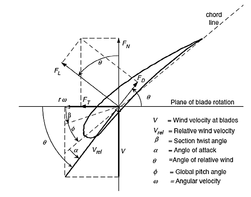
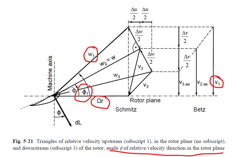
Hello. I designed a 3 bladed HAWT rotor with airfoil S1210 12% from UIUC database. Now, I must validate the results using a blade element momentum method (Chapter 6, sub chapter 6.1 and 6.8 in the book "Gasch, R., & Twele, J. (2012). Wind Power Plants Fundamentals, Design, Construction and Operation"). One of the required parameters is the lift and drag coefficients Cl and Cd.
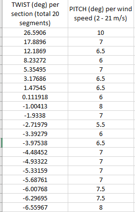
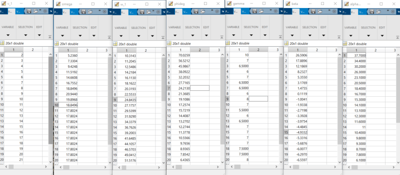
From my calculations using the BEM method (implemented in Matlab), some of my wind turbine blade segments (it has twist per segment) will operate at high angle of attacks.
The problem: I have tried to use the built in XFOIL Direct Analysis feature in QBlade, XFLR5, and even the XFOIL software itself... but every software failed to obtain results for very high angle of attacks. XFOIL did the best and managed to get results up to AoA of 28.5 deg for the high range of AoAs. Thus, I do not have the Cl and Cd values for angles over 28.5 deg, which I suppose the Cl will be very low due to stall. I believe this has something to do with XFOIL not being compatible with stall applications.
As I quote from JavaFoil, another airfoil analysis software:
JavaFoil results will be incorrect if larger areas of flow separation are present. Massive separation, as it occurs at stall, is modeled to some extent by empirical corrections, so that maximum lift can be predicted approximately for "conventional" airfoils. If you analyze an airfoil beyond stall, the results will be quite inaccurate. It is questionable, whether any two dimensional analysis method can be used at all in this regime, as the flow field beyond stall is fully three dimensional with spanwise flow and possibly strong three dimensional vortices.
For the BEM calculation using Matlab, I tried setting the Cl and Cd values for AoA higher than 28.5 deg the same as the Cl and Cd values for 28.5 deg, however the power calculated was still too high at 5500-5600 W. The QBlade multi parameter BEM simulation shows a power of approximately 5000 W. I believe this is because the Cl and Cd values at AoA higher than 28.5 deg leads to lower power, as demonstrated by QBlade multi parameter BEM simulation.
The big question is: which airfoil software is capable of simulating very high AoA, which is obviously post stall operation and has massive flow separation?
Thank you very much!


