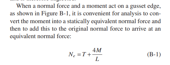
Referring to Appendix B of the guide, why is the normal force Ne=T+4M/L? M produces a force couple and the forces are not in the same direction. Need help understanding this.
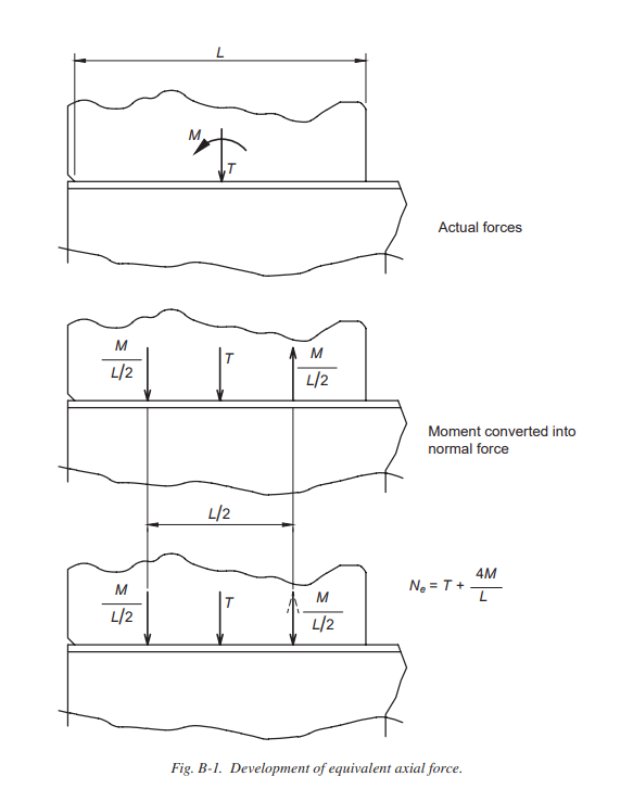
DG29 authors decouple the moment into a normal force, applied at 1/4 points along the gusset edge. Rearranging the moment equation (M=r*L/2), the resultant is r=2M/L.
DG 29 states "The authors base the calculations on the largest resultant normal stress, though obviously the moment will add to the axial stress on one side and subtract on the other" (DG29 pg 371).
The forces acting on the additive "left half" of the gusset edge are N_left_half= T/2 + 2M/L. The above quote, coupled with the reversed dashed arrow in Fig. B-1, leads me to believe the authors intend for designers to neglect the effect of the "right half" (where the normal force T/2 and moment resultant are in opposite directions N_right_half= T/2 - 2M/L).
So if we think about designing each half of the gusset for the additive "left half" forces, we get N_equiv = 2*N_left_half = 2*[(T/2)+(2M/L)]= T + 4M/L.
This is reinforced by the wording on AISC Seismic Design Guide 3rd Ed (blue book), page 5-209. "Over half the gusset, the normal force is N/2 + 2M/L, and over the other half it is N/2-2M/L. For simplicity of calculations, one of the moment forces, 2M/L, is reversed so that a uniform equivalent normal force exists over the entire gusset edge."
Thank you! Your explanation is very well done. I was looking from an equilibrium perspective and couldn't figure out why the guide reversed the load.
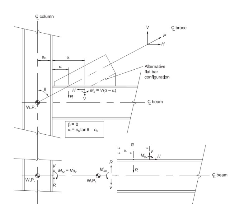
I have one follow-up question for special case 3. The example in the guide only uses M-induced force to check the beam web's local buckling & crippling. But does M (or Mb in the attached figure) alter the internal force in the beam? In other words, should the effect of M be superimposed with the gravity load moment diagram to derive the maximum moment within the beam? I think we should check it per equilibrium - but it is not reflected in the guide.
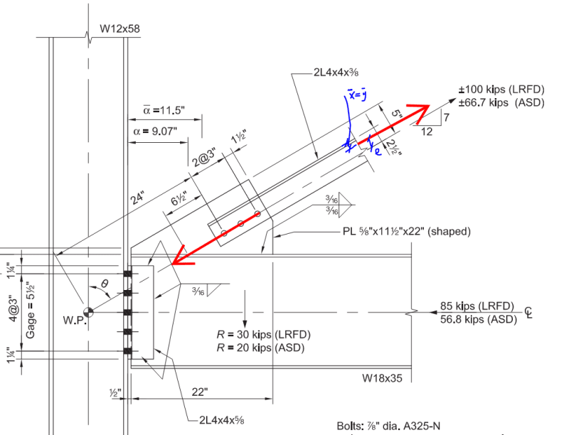
I also have one last question related to Example 5.4. The normal stress should be fairly uniform in the mid-length of the bracing. Hence, the force in the bracing should align with its cross-sectional centroid. On the other hand, the reaction at the bolts should align with the center of the bolt group. Therefore, an eccentricity exists—how should it be handled? I don't see the example acknowledging the eccentricity.
1) The example on DG29, pg 108, uses the additional moment as an "internal force" within the connection. It's probably OK to maintain your current global moment diagram, and only consider additional V & M effects within the connection design.
2) Standard practice under AISC is to ignore the eccentricity in angle braces, as long as they satisfy the stipulations of spec section E5.