StrEng007
Structural
- Aug 22, 2014
- 543
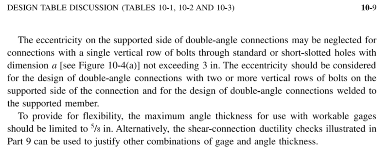
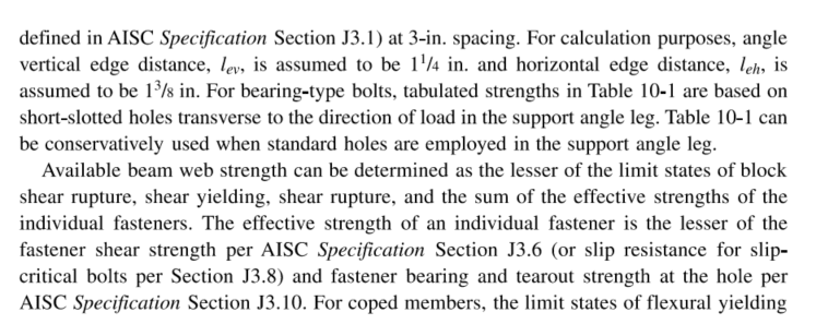
Referring to AISC 360-16, Section J1.2 I understand their statement about Simple Connections.
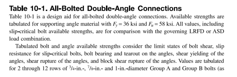
Below is a snapshot from the Manual regarding the simple connections presented in table 10-1:
I've provided a couple images attempting to explain my understanding of the statements above.
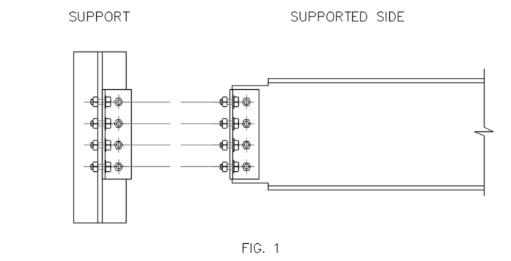
For any given connection, we'll have the supported (beam) side, and the support (another beam or column, etc.) Here (Fig. 1) I'm showing a typical W-beam simple connection to a W-column.
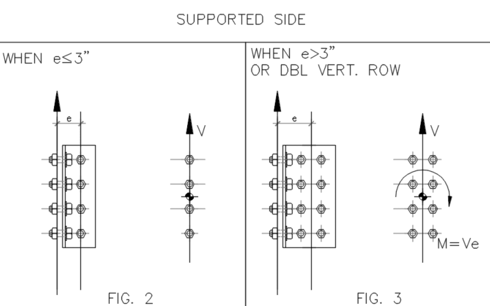
On the supported side, if the anchor bolts have ≤ 3" eccentricity from the support, we can treat this reaction as a simple connection. Here, the support reaction will impart an equal reaction on the bolt group attached to the supported beam's web. This is applied as direct shear through the bolt group centroid, and does not have any additional shear stress due to moment.
However, if there is a double vertical row of anchor bolts at the supported beam, or the eccentricity exceeds 3", we must consider the additional moment in the form Ve.
Assuming the statements above are correct, here is where AISC starts lacking some information.
From the information above, there is no mention about (regarding the bolts connected at the support column) limit state of bolt tension, or combined tension and shear. Naturally, I would assume there would be some form of moment induced tension normal to the faying surface of the bolt connection.
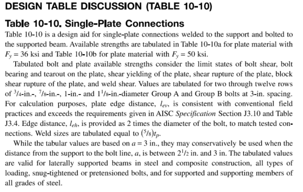
Similarly, how does the same concept apply to a Single-Plate Connection from table 10-10? I don't see how the single plate is not checked for flat bar flexure in addition to there being weld tension normal to the faying surface of the weld? In this situation, to me it doesn't matter if eccentricity exceeds 3" or not, there would always be some form of moment applied to the weld at the support column.
Below is a snapshot from the Manual regarding the simple connections presented in table 10-1:
I've provided a couple images attempting to explain my understanding of the statements above.
For any given connection, we'll have the supported (beam) side, and the support (another beam or column, etc.) Here (Fig. 1) I'm showing a typical W-beam simple connection to a W-column.
On the supported side, if the anchor bolts have ≤ 3" eccentricity from the support, we can treat this reaction as a simple connection. Here, the support reaction will impart an equal reaction on the bolt group attached to the supported beam's web. This is applied as direct shear through the bolt group centroid, and does not have any additional shear stress due to moment.
However, if there is a double vertical row of anchor bolts at the supported beam, or the eccentricity exceeds 3", we must consider the additional moment in the form Ve.
Assuming the statements above are correct, here is where AISC starts lacking some information.
From the information above, there is no mention about (regarding the bolts connected at the support column) limit state of bolt tension, or combined tension and shear. Naturally, I would assume there would be some form of moment induced tension normal to the faying surface of the bolt connection.
Similarly, how does the same concept apply to a Single-Plate Connection from table 10-10? I don't see how the single plate is not checked for flat bar flexure in addition to there being weld tension normal to the faying surface of the weld? In this situation, to me it doesn't matter if eccentricity exceeds 3" or not, there would always be some form of moment applied to the weld at the support column.