Eng-Tips is the largest engineering community on the Internet

Intelligent Work Forums for Engineering Professionals

  • Congratulations waross on being selected by the Tek-Tips community for having the most helpful posts in the forums last week. Way to Go!

Aligning a dimension to a datum axis?

Status
Not open for further replies.

TopPocket

Mechanical
Feb 16, 2022
50
0
0
GB
Here's another one that looks simple but is actually not.

I thought the best way to describe what I want to do was to sketch a wonky drawing of my requirement:

Robot_Guide_Actual_ecw87d.png


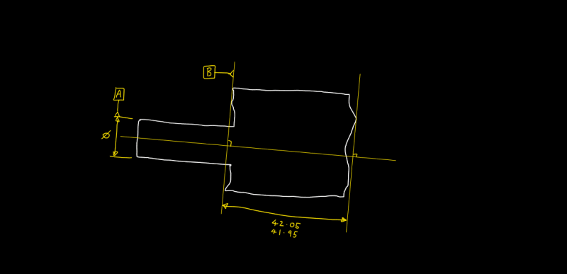
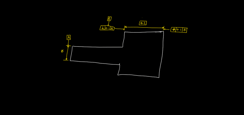
So Datum A is defined as the axis of the small diameter.
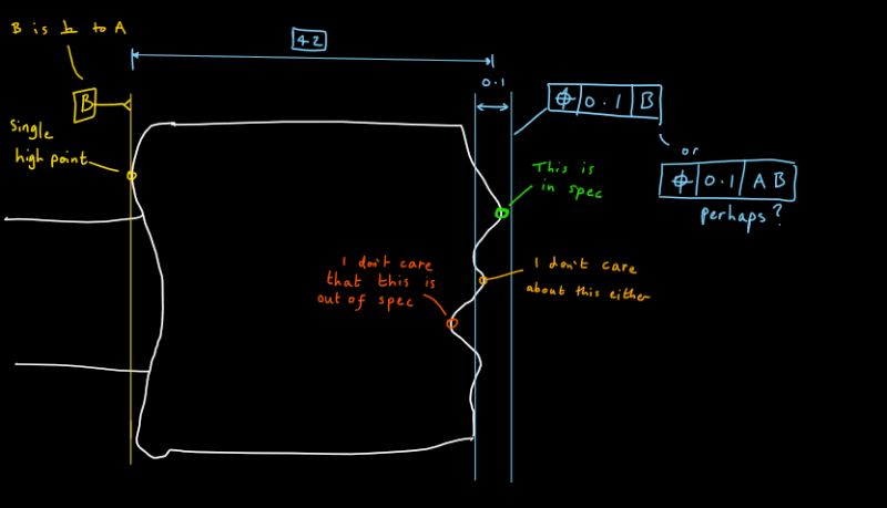
Datum B is then to be perpendicular to Datum A (if required).
Then I wish to define the 42 mm dimension, but the direction the dimension should be measured should be aligned with datum A and be the taken from the most distant points on the two surfaces.

I'm working in ISO so rule 1 isn't default but may be useful to apply?

Technically the 42 mm dimension only needs to apply between datum B and a circular boundary on the rightmost face, but let's walk before we run.

Any help would be greatly appreciated. Maybe it's all dead simple and I'm just too far down a rabbit hole to see the light of day. Here's to hoping hey.
 
Replies continue below

Recommended for you

TopPocket,

In ISO you can apply Position to the surface, so make dimension 42 basic and apply Position 0.1 wrt B to your "rightmost face"

"For every expert there is an equal and opposite expert"
Arthur C. Clarke Profiles of the future

 
TopPocket,

I am an ASME[ ]14.5 guy.

When I draw stuff like this, your datum face[ ]B is my primary datum, with the diameter datum[ ]A feature being my secondary. The diameter simply defines the centre point. Perpendicularity is to the flat face.

Your 42mm length is a feature of size, measurable with a micrometre. It can be rotated with respect to your orienting datum feature[ ]A. You need to control the perpendicularity of datum face[ ]B. Perhaps you could apply a positional tolerance with respect to datum features[ ]A and[ ]B.

What are you trying to do?

--
JHG
 
The most common way to relate a dimensional control to a set of datums is to apply a geometric tolerance. To locate and orient a tolerance zone for a planar feature to datums, per ISO GPS, you can apply either position or profile of a surface. You mentioned that the measurement direction you are interested in is parallel to datum axis A, and the distance you are controlling is from datum plane B. This means that for the geometric tolerance, datum feature A will be the orienting feature that will lock 2 rotational degrees of freedom - therefore it should be the primary datum reference, giving direction to the theoretically exact linear distance that locates the tolerance zone.
The secondary datum reference B will then establish the origin for that linear distance. Note that the datum axis and plane will be perfectly perpendicular to each other, so with A providing the orientational constraints, the simulator for datum B will not make full contact with the actual face of datum feature B. It may contact as little as one high point.
 
Thanks for the responses.

CheckerHater:
I did consider using Position like you say although I've found not many people interpret it correctly.
Further more I'm not sure it completely covers my situation. I only care about the highest point on the face - with the "height" direction defined by A. If a point falls below the spec I still want to pass it. See this drawing to see what I mean:
Robot_Guide_Position_luremw.png

I would want this to pass.
The green point is the one I care about the orange one would fall outside of the tolerance bounds but I wouldn't want it to make the part fail.

Also If my position calls AB rather than just B am I right in thinking it will be oriented to A and then B or is that just further constraining the point? Should I define B as coming off a perpendicular dimension and just call out B? See Image below:
Robot_Guide_Datums_vdnhka.png

Would this be the correct way to datum it?

Drawoh:
I understand why you would want to do it this way, however I need A to be my primary datum as this reflects how the part is used. To be honest there should probably also be a surface straightness on that OD too to restrict any taper.

Burunduk:
Thanks for translating my picture into words, it seems you have got the gist.
Are you saying that the primary datum defines the orientation of dimensions in the same direction?

You're interpretation of the datum feature B only contacting on a single point is correct as this replicates function and is what I want to correctly define.
The way datums are constructed allows this scenario to occur, the question is how do I construct the same scenario on the parallel face? It's almost like I want to construct a third datum C on that face and put the 42 mm dimension between the datums B & C, although I'm pretty sure this isn't correct practice. Hopefully it helps illustrate what I'm after though?
 
TopPocket said:
the question is how do I construct the same scenario on the parallel face?

You can use the circled T modifier after the tolerance value. It's the "Tangent associated toleranced feature" symbol. I think it was added only in the 2017 version of ISO 1101, so if you are following an older version, you won't be able to use it. This specifies that the feature you are controlling is the plane tangent to the feature at the highest points (not quite the highest point contacted by a plane perpendicular to datum A, but maybe close enough). Could this answer your needs?

TopPocket said:
Are you saying that the primary datum defines the orientation of dimensions in the same direction?
The short answer is yes.
The primary datum is usually what orients the part relative to the datum reference frame ("datum system" in ISO GPS) by locking at least two rotations. Since the TEDs are related to the datum system, their directions are dependent on the primary datum in the considered feature control frame.
 
CheckerHater:
After trying to parse the standards (why so dry [upsidedown]) I vaugely get what your suggestion is doing.

To me though using an (E) would mean the same thing though? The orientation parallelism keeps the measurement planes perp to A.
42_tolerance_proposal_c8t4fi.jpg
 
Burunduk:
Thanks for introducing me to another letter in a circle and thanks for explaining its meaning using normal language. Looking at the ISO explanation: "(T) shall be used to indicate that the toleranced feature is the associated tangent feature based on the L2 norm with the constraint that the tangent feature is outside the material of the non-ideal feature." has me bleeding from the eyes.

If I've interpreted it right this is kind of what I would expect to happen if perfect plane was rested on the surface - like how a primary datum plane is typically fitted to a face. But wouldn't that mean the plane created by the (T) modifier wasn't parallel to Datum B? If so, how can a size be measured? This (T) modifier actually seems more relevant to my other post.
And you know it probably will suffice but I'm too deep now to not get to the bottom of it.

With regards to your second point, if the dimension direction is assumed to be parallel to the Datum A then does that negate the need for the parallel plane indicator suggested by CheckerHater? To be honest I never understood where those things might be needed.

If that was the cause isn't the solution just the one in my sketch above? No need to even define the B datum. Although if I did want to apply it to a boundary on the face that wouldn't work and I'd have to figure out the position method.

Is it allowed to put an (E) modifier on a basic dimension?

Thanks
 
TopPocket said:
But wouldn't that mean the plane created by the (T) modifier wasn't parallel to Datum B? If so, how can a size be measured?

Yes it would mean that the tangent plane won't be parallel to datum plane B, or perpendicular to datum axis A for that matter.
When you use a geometric tolerance, the TED distance is not measured directly, but the feature is evaluated for fitting in the tolerance zone. The rate of fitting in the tolerance zone is quantified by the measured value, which is in case of a location control applied to a surface, the distance from the "nominal" (TED/basic) geometry to the point on the surface that deviated the most, doubled - to represent the utilized portion of the tolerance zone.
If circled T is applied, replace the farthest point on the surface by the farthest point on the tangent plane - but it's the same principle.

As for your question that relates to the parallel plane indicator, I will have to research the topic before giving any answer, as I'm way more ASME than ISO.

I'm pretty sure the circled E can't be used with a basic dimension, because the envelope principle has to do with interpretation of directly toleranced size dimensions.

Out of curiosity, if you're used to ISO, how come you use the term 'basic dimension' over 'theoretically exact dimension'?
 
TopPocket,

(E) may not do it. It means your "orange" points may be rejected if they are outside of "envelope".

(LP) is two-point size and (GN) is minimum circumscribed size.

For external features (E)=(GX)+(LP) and you need (GN)+(LP)

"For every expert there is an equal and opposite expert"
Arthur C. Clarke Profiles of the future

 
Looks like Table 8 in ISO 1011:2017, "Application cases for intersection plane" invalidates the use of an intersection plane parallel to a datum axis.

Also, it seems like the intersection plane indicator is intended to define direction for sampled line elements controlled by geometric tolerances such as straightness, profile of a line, and orientation tolerances such as parallelism of line elements, so that the orientation in which these line elements are obtained is not dependent on the direction of the 2D drawing view projection.

Maybe ISO 14405-1, the standard that defines the meaning of symbols such the suggested LP and GN has something about the direction of 2 point measurements, and maybe the interpretation for use of these symbols in conjunction with an intersection plane, but I have no access to that standard.
 
Burunduk, the reason I'm always mixing my terminology is mostly due the lack of accessible literature on ISO and there being a lot of decent resources on ASME. This coupled with there being 95% overlap between the two means that often I'll start with the nice ASME books to get an understanding of what I'm after and then decipher the ISO to see how it deviates. Basic is also just less of a mouthful. MMC instead of MMR is another one I always see being used in general discussions. Most of the time it's fine as the ultimate goal is communication of concepts between individuals.

But here in the nitty gritty I can see the nuance being more important so I will try check myself.

Thanks for the Tangent Modifer - this one is super useful, relatively simple to explain and easy to implement on a CMM.

I'll have to weigh up whether using (LP) and (GN) is worth the inevitable confusion it will cause. Turns out the manufacture of the parts in question may actually be stable enough to not warrant this extra scrutiny.

My desire for accurately describing what I want needs to be balanced with the lack of understanding of the manufacturer who I've found will rarely ask for clarity likely to protect their pride. (This is why the Tangent Modifier is so nice as, if ignored, any passing parts would still have been accepted if it wasn't)
 
Check and double-check evaluation with CMM. Maybe it isn't so easy to implement the correct evaluation of tangential plane on a cylinder. Because one of the 4 corners will be evaluated and will almost always throw out the worst corner, which extends over the edge of the actual surface, so the true value may not be so bad.
 
Status
Not open for further replies.
Back
Top