rollingcloud,
What I meant is to create a datum reference frame that will fully constrain the tolerance zone for the entire crown of teeth, and by that the 3 specific teeth that need to be centered to the holes will need to be controlled correspondingly.
The datum feature selection should be based in functionality.
Here is a full suggestion:
The OD of the part could be datum feature A, and it would provide a datum axis and the simulator of it would constrain 4 degrees of freedom. The pattern of 3 holes will be datum feature B referenced at MMB, and its simulator (3 fixed size pins) will constrain the remaining 2 degrees of freedom, including the rotation about datum axis A, and providing a datum which is 3 axes and a point. Datum axis A will define 2 perpendicular planes of the datum reference frame intersecting at it, and the three axes of datum B will lie in the third plane. The three datum reference frame planes will form the axis system for measurement.
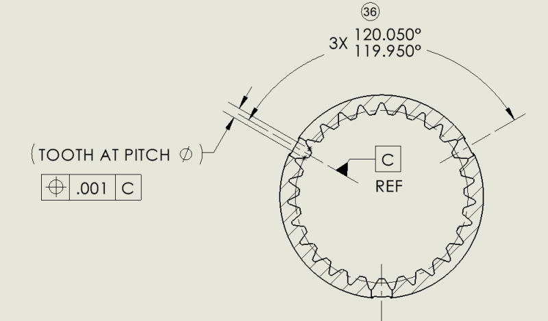
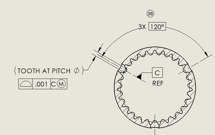
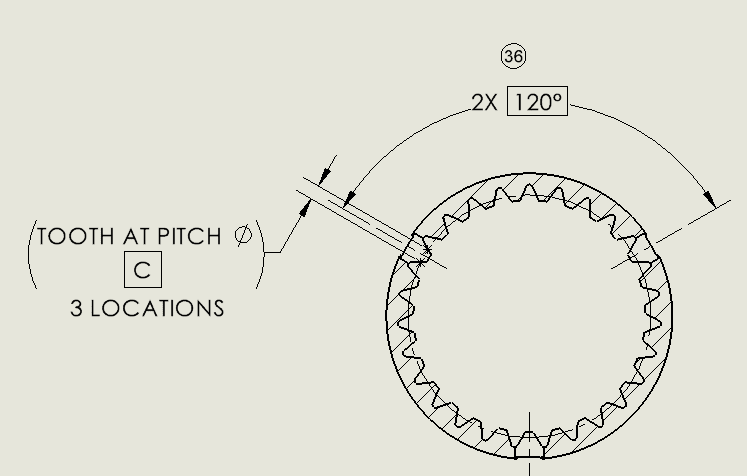
The entire geometry of all teeth could be specified by basic dimensions. A surface profile tolerance feature control frame would point by a leader to the outline of one of the teeth with an all-around symbol, and this will require all teeth to fit in the tolerance zone. The tolerance value could be adequately tight to control the size, form, orientation, and location requirements of all features forming the crown of teeth. Alternatively, if different tolerances are preferred for different groups of features, there could be several feature control frames with the number of places indication, all referencing datum features A primary and B secondary and thus bounded by a simultaneous requirement. The three teeth that need to be centered to the 3 holes that are datum feature B will need to conform to a tolerance zone that governs it - because the rotation around datum axis A is locked by the pins simulating datum B which is associated with these holes.