Continue to Site

Eng-Tips is the largest engineering community on the Internet

Intelligent Work Forums for Engineering Professionals

  • Congratulations KootK on being selected by the Eng-Tips community for having the most helpful posts in the forums last week. Way to Go!

Alignment pegs GD&T

Status
Not open for further replies.
Replies continue below

Recommended for you

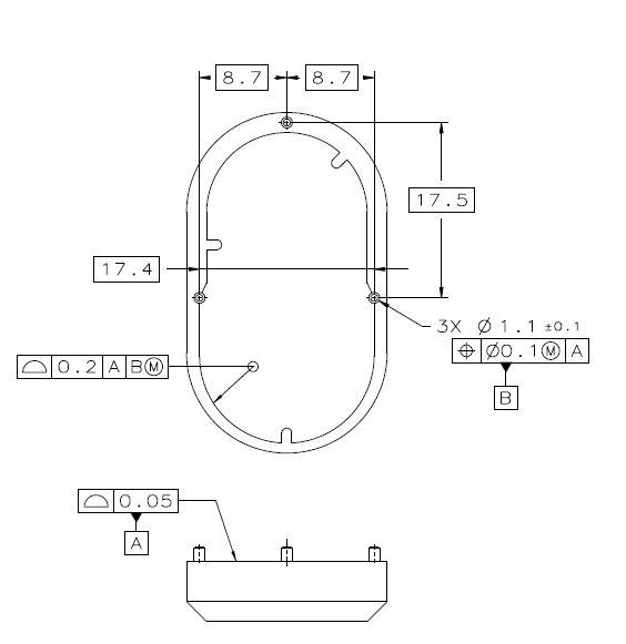
PINS_fca2vd.jpg


Primary datum reference A locks 3 degrees of freedom: 2 rorations (initial stabilization), and 1 translation. Seconday datum reference B locks the other 3 degrees of freedom: translations in 2 directions, and the remaining rotation.
MMC, MMB as shown appropriate if the main concern is about the parts fitting together and less about alignement.
 
Thank you Burunduk. The datum A i guess is flatness but you have profile mentioned and also the profile feature 0.2 A B, is that necessary? I don't really care much about the inside face.
Also the drawing follows iso standard if I am not wrong?
 
What I have shown is valid according to the ASME Y14.5 standard. If you follow the ISO standards, I think you won't be able to use the circled M following the datum reference in the "tolerance frame" to provide the additional variation which is called in ASME "datum shift". The MMR following the position tolerance is valid.
It makes the most sense to control the rest of the part features with profile referencing A primary, B secondary. It will control the form and size, as well as location and orientation of the surfaces with respect to the "datum reference frame"/"datum system". The all-around profile on the internal geometry was just an example. You can choose the tolerance values. If you have any features critical for function, control them with a tighter tolerance. If nothing is particularly important, you could specify a loose general profile tolerance on all surfaces, and direct to the CAD model for query for all the basic dimensions that are not specified.
 
Thank you Burunduk. Things make more sense now.
 
You're welcome.
BTW, please ignore the basic dim. 17.4 in my suggestion sketch. It is redundant.
 
Okay👍. Btw this might be dumb question but you mentioned that you used ASME Y14.5 in the drawing but I see that you used 3X instead of 3PLACES for specifying the pins but isn't 3X iso? Is it okay to mix standards that way?
 
It is the same in ASME.

"Repetitive features or dimensions may be specified by the use of an X in conjunction with a numeral to indicate the “number of places” required"

It is para. 1.9.5 in the 2009 edition and 4.6.5 in the new (2018) edition.

In ISO lowercase "x" is used.
 
Ah didn't know that. Thank you. I guess it's time to switch from iso to asme.
 
Good idea. You will have all the rules and practices documented in one place (Y14.5) rather than scattered between many documents (1101, 5458, 5459 etc.) that do not get updated simultaneously and you need to keep track of them all.
 
Hello Burunduk, is it correct for me to understand that in your drawing where the pins are used as locating features, it is independent of the outer surface of the device? So in an assembly, it will always fit but the outer surfaces may not align and one way to control that is to put an outer profile feature frame as you did with the internal profile feature.
 
Hi Sharudu,
Yes, you are correct.
My example is not a complete drawing. All other surfaces of the part, including the external geometry, can be controlled with reference to datum features A and B.
 
Status
Not open for further replies.

Part and Inventory Search

Sponsor