Continue to Site

Eng-Tips is the largest engineering community on the Internet

Intelligent Work Forums for Engineering Professionals

  • Congratulations KootK on being selected by the Eng-Tips community for having the most helpful posts in the forums last week. Way to Go!

Allowable Bearing Stress AISC

Status
Not open for further replies.

CraneEng87

Mechanical
Dec 23, 2015
21
Hello,

I am using AISC Steel Construction Manual 9th Edition attempting to assess a bolted connection in shear. The manual says under Chapter J page 5-74 that the allowable bearing stress for a standard hole with two or more bolts in line of force to use the below formula.

Fp = 1.2Fu

Fp is the allowable bearing stress, ksi
Fu is the specified minimum tensile strength of the critical connected part, ksi

My question is what is "minimum tensile strength"?

My first thought is Ultimate strength however the 1.2 factor would make my allowable exceed it and I've never seen an allowable anywhere near Ultimate.

Any Ideas?
 
Replies continue below

Recommended for you

Take a read of the Commentary on this section (J3.7) on page 5-168 of the AISC 9th Edition.

The F[sub]p[/sub]=1.2F[sub]u[/sub] is indeed based upon the tensile strength of the thinner connected material, and the criteria is based upon 'allowable' deformation around the bolt hole. Tests have demonstrated deformation magnitudes of approximately 0.25 in at 'ultimate-type' conditions.

If bolt hole deformation is a design consideration then you can adopt a lesser allowable bearing stress.

More current AISC editions (based upon LRFD methodologies) have adopted the following, from RCSC's 'Specification for Structural Joints Using High-Strength Bolts':

Capture_egsrzt.png


Keep in mind that the above Equation 5.3 would be applicable with a φ (resistance factor) of 0.75 with factored loads, or a Ω (factor of safety) of 2.0 if using allowable applied loads.
 
Thank you both for the great responses.

I never knew they gave a span on the tensile strength of material. The reference to minimum makes sense now. The chart SlideRuleEra referenced was helpful.

Ingenuity:
I am not very familiar with LRFD, my customers have always favored the ASD of the old edition. My customer is usually very conservative and only allows us to use 85% of AISC allowables.

Since I don't want any deformation around the holes I will use the 1.0Fu then take my 85%. Unless I'm close I don't see any reason to account for an additional 20% in the allowable.

 
CraneEng87 said:
don't want any deformation around the holes I will use the 1.0Fu then take my 85%. Unless I'm close I don't see any reason to account for an additional 20% in the allowable.

Seems to be a perfectly reasonable approach.

I assume you don't have any bolt holes that are too close to any edges.
 
No, I'm using 3/4" bolts in 13/16" holes. My nearest edge is 1 1/4" away which should be fine according to Table J3.5.
 
CraneEng87

I counter some responses above, the 1.2 is based on a diagram of the bolt bearing/shear breakout. AISC limits capacity to the lesser of shear breakout and bearing. The 1.2 is for shear.

You get 1.2 because:

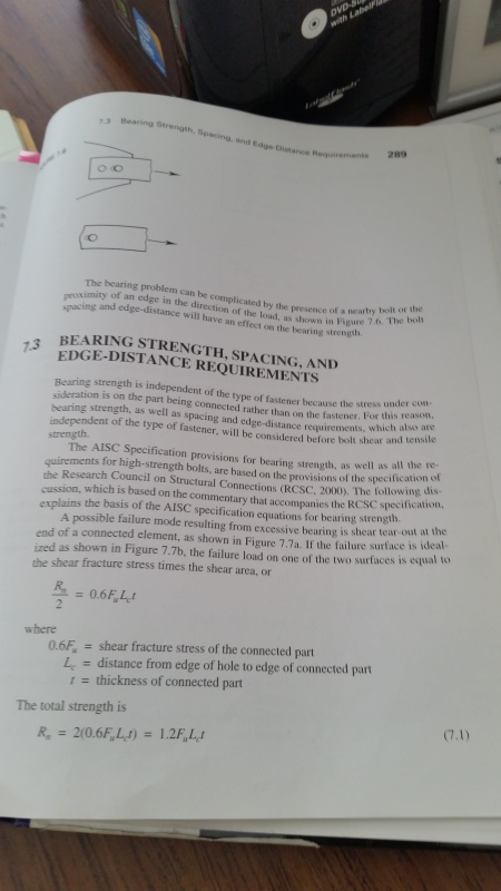
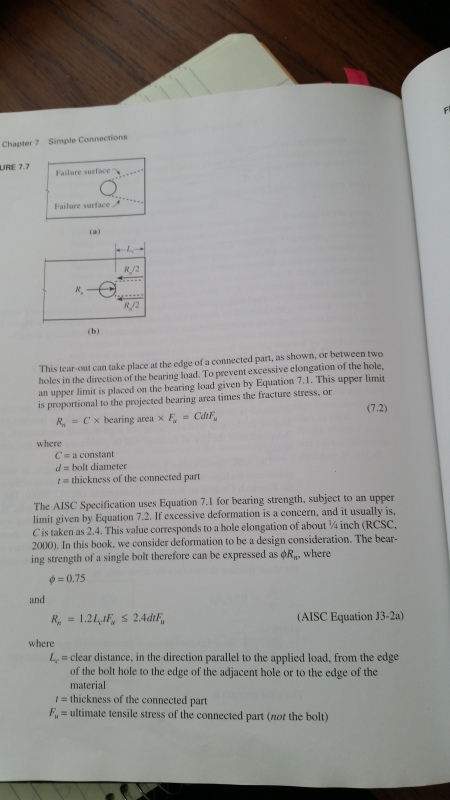
There are two failure planes each weith a length of Lc and thicktness T, with a shear stress capacity of 0.6Fu. So putting it together you get the equation J3-2A where capacity is equal to 1.2Lc*t*Fu. See devrivation below from textbook

1.2 is correct you aren't exceeding the allowable or being unconservative.

AISC_Bearing_Stress_2_q2rtqb.jpg


AISC_Bearing_Stress_s4txnb.jpg


In regards to "Fu is the specified minimum tensile strength of the critical connected part", you need to remember to check both members of the bolted connection.

Jeff
Pipe Stress Analysis
Finite Element Analysis

 
Jeff:

The 9th Edition that the OP referenced is based upon allowable stresses and that '1.2' is based upon the projected area of the bolt for bearing. The 9th edition has separate conditions for the bolts at edges/ends for shear tear-out of:

F[sub]p[/sub]=L[sub]e[/sub]F[sub]u[/sub]/2d<=1.2F[sub]p[/sub]​

Somewhat co-incidental (?) that LRFD editions also has a '1.2' factor, but this is for shear tear-out of two failure planes (as you stated) whilst the '1.2' in the 9th Edition is for bearing.

If deformation around the hole is NOT a design consideration the 9th edition allows bolt bearing stresses of 1.5F[sub]u[/sub].
 
Status
Not open for further replies.

Part and Inventory Search

Sponsor