Eng-Tips is the largest engineering community on the Internet

Intelligent Work Forums for Engineering Professionals

Allowable Nozzle Load Curve for Integrally Geared Comp 2

Status
Not open for further replies.

msii

Mechanical
Nov 1, 2017
44
0
0
AU
Hi all,

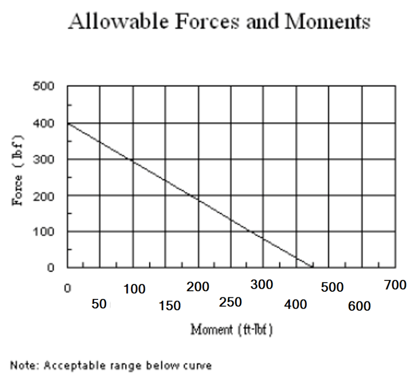
I have a curve from a compressor supplier that provides Allowable nozzle loads based on the attached values (A line between Maximum force and maximum Moment). When I do Caesar II analysis I get Fx, Fy, Fz, Mx, My, Mz values at the nozzle location. How can I relate the F and M values with the curve provided by the supplier? ِDoes it mean that I need to find the resultant values of F and M (sqrt(Fx^2+Fy^2+Fz^2) and sqrt(Mx^2+My^2+Mz^2)) and compare them with the maximum values provided in the curve?

2024-png_shzfku.png


Thanks for your help
 
Replies continue below

Recommended for you

The charts are for one total force and one total moment. But why two same charts? I don't know. They may refer to X and Y components.

Nozzle limits typically refer to Principal forces and moments, those normal to the nozzle plane, an axial load "Z" component, and shear (or reactions) in "X" and "Y". Moments in X, Y and a Torsion about Z. I believe you should only find the resultant for the X and y components. Z force is axial load and Moment about Z is Torsion.


--Einstein gave the same test to students every year. When asked why he would do something like that, "Because the answers had changed."
 
Without any other indication I would have to assume resultant force and moment. They want you to plot (M_r, F_r) on the chart and if you are below the line you are good, above the line, not good.
Two charts, one for the suction and one for the discharge connections perhaps?
 
Man I hope those are small nozzles those are pretty low combined loads. I'm surprised they don't have a table for each nozzle and load orientation.
 
Best to contact the manufacturer and ask them. Don't make any assumptions.

Also - Make sure you include some kind of stiffness in the model for the flexibility of the flanges. Model the flanges as a flex anchor. The flanges are not infinitely stiff, which is the CAESAR default assumption. This makes a huge difference on the magnitudes of the calculated reactions. You can ask the manufacturer if they have stiffness values for the flanges, but they will likely say huh? when you ask them that. So next thing is to estimate it. You can get pretty reasonable stiffnesses from an FEA model of the compressor, if you have access to FEA. NozzlePro can make a reasonable model of a compressor. Failing those two, you have to use horse sense. 1E6 lb/in is a good place to start; see if that passes your straight-face test.

 
Kern. I do prefer horse sense. Those load limits are very typical and should not be a challenge to make the pipe stiffness less than an anchored pump. We've been doing it for years without including nozzle stiffness or having Caesar's help. It is not advantagous for the pump companies to let us start risking warping their flanges or casings. And then you will no doubt increase the loads without knowing the allowable forces on the pump casing or vessel walls. Those loads do transfer somewhere. Plus last, but not least, overloading the flanges will void the equipment warranty. I doubt FEA or NozzlePro will come to your rescue. As they say, read the fine print. :)


--Einstein gave the same test to students every year. When asked why he would do something like that, "Because the answers had changed."
 
1503 - I gently submit you misread my post. Having done this for nearly 40 years now I know from where I speak and I got the bruises to show for it. My procedure above works every time. Please explain how you concluded that my procedure will end up in 'warped flanges'.

There are PLENTY of installations where it is not possible to achieve published allowables because the piping and installation simply do not have facility for adequate flexibility: short runs, high temperature, SS pipe, large diameter pipe, or combinations of those. In this case, it is incumbent on the flexibility analyst to take every means possible to ensure the flexibility model is a reasonable facsimile of physical reality.

Utilization of flange stiffnesses in a flexibility model is a 'pencil sharpening' adaptation. The base assumption of infinite stiffness is a starting point; if the model passes allowables, then you're good. If not, you must add nozzle stiffness, use an expansion joint, or add flexibility to the piping.

If you have a better procedure, proven by past experience, then by all means use it. You are 100% free to ignore what I submitted. The OP asked for help and opinions, and I submitted mine in good faith. Do you really think I would advocate a procedure that will end up in 'warped flanges', as you put it?

 
I only said I prefer horse sense. No critism was intended. I understand the issues. I only included some potentially very important commercial considerations you did not mention.

Yes, I agree the allowable loads are probably not realistic, however damage does seem to be possible by exceeding allowable loads no matter what they are. The lawyers will pick up on that. Even if you beef up with actual stiffness, or overload does not cause damages, you still will be on the hook if the pump experiences alignment or almost any other chronic problems. Avoiding any potential warranty issues on pumps that can cost millions is important and this seems like a risky stragegy all the way around. So right, its not for me.

--Einstein gave the same test to students every year. When asked why he would do something like that, "Because the answers had changed."
 
OK. When I say 'Stiffness' I'm referring to the classical Hookean definition of stiffness, that being the k in Hooke's Law: force (or stress) = stiffness * deflection. Stiffness is also known as flexiblity.

In our case here, stiffness in a pipe stress model is a representation of how flexible the compressor flanges are. Not just the compressor flanges, but the piping, pipe supports, compressor foundation, etc.

If you recall the basic beam flexure formula S=My/I, it can be rearranged to solve for a stiffness k which is deflection per unit load. Another version of Hooke's Law is S=E*epsilon, where epsilon = strain, aka deflection.

Lawyers... let's say there's a failure, with subsequent litigation. The other side will bring in SMEs that will ask you if the stress model of the piping system was properly configured, to include a representation of the flexibility (stiffness) of all components of the system: piping, flanges, supports, foundation, everything. If the piping system model is not up to snuff, you will be hung out to dry because the case will be made that you did not exercise what is called the 'reasonable man standard' of care and custody, i.e. what would another similarly-qualified person have done in this situation.

We have to remember these systems are covered by the ASME B31.3 piping code. That code has very specific requirements for piping flexibility analysis. Some type of flexibility analysis is mandatory by the code. Horse sense is a perfectly acceptable way to do pipe stress. I do it all the time. But I make damn sure that it is applied to the proper situation. Rotating equipment is not typically one in which I would apply horse sense because there is no way with horse sense to quantify how much load is being applied to the flanges, and without a properly-configured stress model I can't conclusively show whether the system complies with the allowables, especially on gas compressors because they always have hot discharge piping between the discharge and the aftercooler (if an aftercooler is present).

If you, as the person of record on the project, can say that you have installed X number of nearly identical systems with zero failures, then that method will satisfy the intent of the code.

Bottom line: Whether or not you apply stiffness/flexibility in your stress model, or whether or not you need to even run a stress model, is a risk analysis and code compliance issue.


I'll just say that I have always managed to make the pipe more flexible than the compressors, pumps and vessels without depending on flange movement, even with unrealistic allowable loads. I have also fixed a number of installations where pipe loads were causing misalignment of compressors just by relocating a few clamps to the pipe leg on the other side of a 90° ell. I have never needed to resort to expansion joints. A little bit of flexibility goes a long way and is far cheaper than making just one major compressor realignment. Half of all stress problems are caused by analysis program requirements to have at least one anchor, in order to keep the computer model from sliding off the monitor, and the engineer just put that anchor at the first point he marked up in the iso, right at the compressor flange, rather than at some point in the middle of the piping system. I find it's pretty easy to beat the system, if you just use 2 or 4 90s and put the anchors in the right places; i.e. not on equipment flanges.

--Einstein gave the same test to students every year. When asked why he would do something like that, "Because the answers had changed."
 

Uhhh.... all I can say is you've had the C team on your projects. There is zero requirement for an anchor to be in any line in any stress analysis software. The line just has to be properly supported. Also, if he used a full anchor, there's one more point of evidence you had the C team.

Stress analysis/piping flexiblity/FEA is like any other computer software: GIGO. It's 100% on the operator to get it right... and his QA checker. What? No QA checker? Find a different engineering firm.

I'll just say I've done flexibility analyses on many many thousands of hp of pumps and compression over many years and I've never had some contractor deviate from the design drawings because "it didn't look right". I'm not one to roll the dice when it's not warranted. I'm sure you've done the same.

The code is the code. Manage the risk as you see fit.


Definitely the F team.
As for the rest, I cannot possibly get away with ignoring manufacturer's requirements. No chance.

--Einstein gave the same test to students every year. When asked why he would do something like that, "Because the answers had changed."
 
I always model the flange of connection to rotating equipment as an anchor. There is no way of determining the actual stiffness of the connection. The connecting flange is basically rigid. What is flexible is the entire structure of the pump or compressor, etc. which is an unknown. The equipment manufacturer doesn't even know this. To be conservative if you determine the forces and moments developed by modeling as an anchor you can't go wrong. Now for a connection to a pressure veseel there are methods to calculate the actual flexibility so I would always include flexibility for connections to a pressure vessel or tank.
 
Yes - this is the first (most conservative) assumption and is always tried as the first cut.

Correct. But there are ways to get reasonable approximations that are defensible. FEA is one way. Judgment-based SWAG is another. If the system does not pass allowable flange loads, and if you are stuck with the piping layout you got, then you have to sharpen your pencil/make your model more physically representative.

One way to do that is by adding flexibility to the model's boundary conditions (the supports and the equipment flanges). For example, if you model a compressor flange as rigid (1E9 lb/in in all six DOF) and it doesn't pass, can you reduce the stiffness to 1E6 lb/in in all six DOF? What about just three of the DOF? Most folks would agree that any pump ever made is way less stiff than a MILLION pounds per inch at the flange. That's just an example of a way to approach this. You can also add support stiffnesses into the model, and that usually helps a lot. Sometimes adding support stiffness is enough such that you don't even have to mess with equipment stiffnesses. In my experience, sometimes folks get tunnel vision and forget their basic mechanics and just end up running the software. As Edward Klein says: all the world's a spring.

In real life an equipment flange is not rigid. Not even close. If it was, there would be no need for allowable flange loads. Any equipment flange or housing will deflect a few thousandths by even a very small force or moment. The problem arises when those loads get large enough to deflect the housing enough to deflect the shaft thus disrupting the alignment of bearings and seals. Allowable loads are there to prevent that very thing from happening.


This is the F team.
Total waste of good concrete.

Anchor_Block_-_world_record_size_f8gljv_cf7zbr.jpg


--Einstein gave the same test to students every year. When asked why he would do something like that, "Because the answers had changed."
 
A gravity wave attractor (for powering gravity flow pipelines).
Assures that the outlet can never rise higher than the inlet?

Capping off the entrance to the Jinn's cave?

Proof that not all black holes are spheres?

A 500 tonne thermal anchor.
By someone who didn't believe in virtual anchors.

I used that picture for a presentation in Abu Dhabi on how to design virtual anchors, add flexibility and ... save $5,000,000.

Really nice pipe rack though.


--Einstein gave the same test to students every year. When asked why he would do something like that, "Because the answers had changed."
 
Status
Not open for further replies.
Back
Top