Hello All,
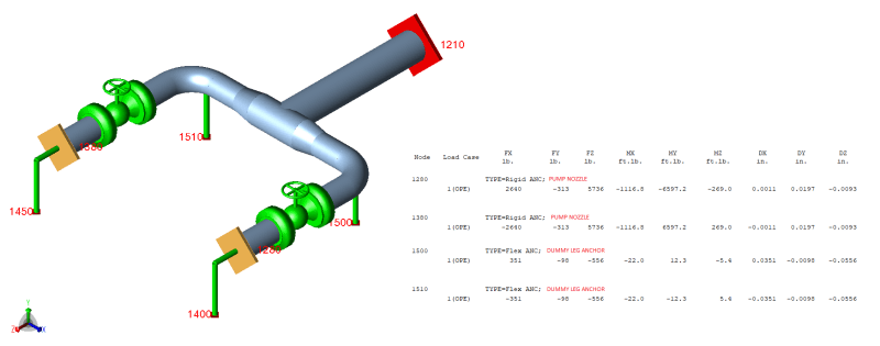
I am new to pipe engineering, and I am trying to do pipe stress analysis to learn the software(Autopipe). I would like to get your opinion on routing the followng pipe based on your experience to reduce the nozzle load on the centrifugal pumps. I would also appreciate if you could point me out to good resource for pipe engineering best practices.
Info:
Medium - Water
Ambient temp - 15 C
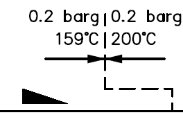
Temperature - 95 C
Material - A312- TP316L Stainless steel schedule 10
Pipe Size - DN150
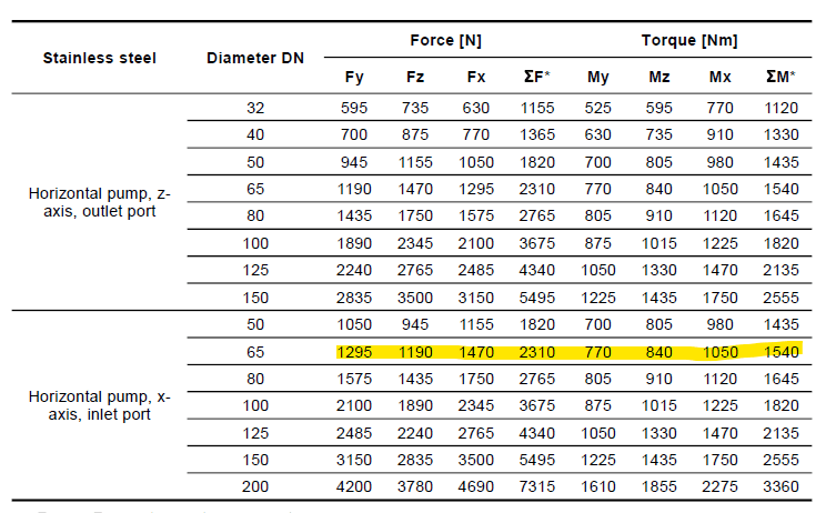
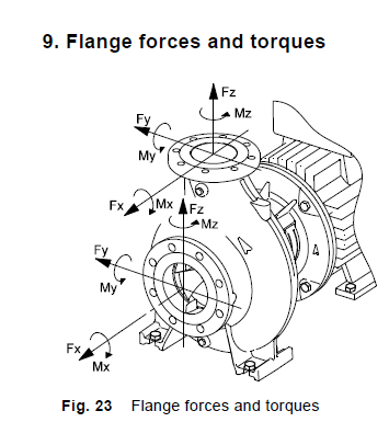
Pump Suction - DN65
Constraints -
Pumps and tank cannot be moved
Height of the pipe cannot be altered, any expansion loop must be horizontal
Pumps may run in any configuration i.e. they can run simultaneously or may work on single pump(either or)
Prefer not to use expansion bellows
Layout drawing attached. Any help/advice would be appreciated.
Thanks.
[URL unfurl="true"]https://res.cloudinary.com/engineering-com/image/upload/v1714961534/tips/0092_001_jfmqym.pdf[/url]
I am new to pipe engineering, and I am trying to do pipe stress analysis to learn the software(Autopipe). I would like to get your opinion on routing the followng pipe based on your experience to reduce the nozzle load on the centrifugal pumps. I would also appreciate if you could point me out to good resource for pipe engineering best practices.
Info:
Medium - Water
Ambient temp - 15 C
Temperature - 95 C
Material - A312- TP316L Stainless steel schedule 10
Pipe Size - DN150
Pump Suction - DN65
Constraints -
Pumps and tank cannot be moved
Height of the pipe cannot be altered, any expansion loop must be horizontal
Pumps may run in any configuration i.e. they can run simultaneously or may work on single pump(either or)
Prefer not to use expansion bellows
Layout drawing attached. Any help/advice would be appreciated.
Thanks.
[URL unfurl="true"]https://res.cloudinary.com/engineering-com/image/upload/v1714961534/tips/0092_001_jfmqym.pdf[/url]