Continue to Site

Eng-Tips is the largest engineering community on the Internet

Intelligent Work Forums for Engineering Professionals

  • Congratulations waross on being selected by the Eng-Tips community for having the most helpful posts in the forums last week. Way to Go!

Excessive Pump Nozzle Load - Suggestions to reduce it? 6

Status
Not open for further replies.

Gears6580

Mechanical
May 5, 2024
8
Hello All,

I am new to pipe engineering, and I am trying to do pipe stress analysis to learn the software(Autopipe). I would like to get your opinion on routing the followng pipe based on your experience to reduce the nozzle load on the centrifugal pumps. I would also appreciate if you could point me out to good resource for pipe engineering best practices.

Info:
Medium - Water
Ambient temp - 15 C
Temperature - 95 C
Material - A312- TP316L Stainless steel schedule 10
Pipe Size - DN150
Pump Suction - DN65


Constraints -
Pumps and tank cannot be moved
Height of the pipe cannot be altered, any expansion loop must be horizontal
Pumps may run in any configuration i.e. they can run simultaneously or may work on single pump(either or)
Prefer not to use expansion bellows

Layout drawing attached. Any help/advice would be appreciated.

Thanks.
Screenshot_2024-05-06_134455_yg9vyl.png

Screenshot_2024-05-06_134534_jtsiee.png

[URL unfurl="true"]https://res.cloudinary.com/engineering-com/image/upload/v1714961534/tips/0092_001_jfmqym.pdf[/url]
 
Replies continue below

Recommended for you

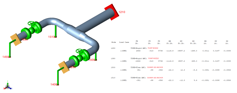
For reference I ran a very quick and simple pump suction model - basically coming straight out of a tank (ignoring those loads) and going to a suction header to the pumps. Modeled the pumps the way I normally would with rigids and modeled the suction piping dummy leg anchors as rigids as well with 1E4 stiffness on the anchor at the bottom of the dummy leg.

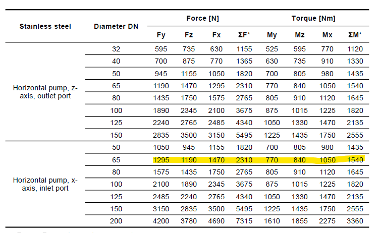
The pump nozzle loads aren't terrible given the pipe anchor flexibility, but those loads are still much higher than the published values for a Goulds 3196 or similar type of process pump. And if there becomes a damage/warranty issue and the model shows something like this, you have no outs.
Pump_Example_zl4dbg.png
 
Gears6580

You have inherited an extremely poor equipment layout. Three feet between pumps. That's unheard of.
Anyways, you say 6" pipe to 2.5" pump nozzle. Review line size reduction based on flow at tee split.
From Pump, do size reduction, minimum straight run, and turn away from the pumps, so you can create flex between pump and tank.
First try, go out 3 feet from pump line and turn, next leg towards tank run 6 feet. Join lines together at tee.
At this point run this wing loop shape for your hot/cold design conditions, restrain tee 4 sides.
Once you get the loop between pumps to be close, run the pipe to the tank with a loop to suite.
Also, thermal analysis on hot tanks and vessels is taken from the center line, after all it does grow with heat.

Good luck
Mike
 
How on earth are you getting that kind of temperature and pressure for water from a storage tank?

The first thing you need to do is talk to the process engineer and get some realistic conditions. They've created a problem for you that probably doesn't actually exist.

Edward L. Klein
Pipe Stress Engineer
Houston, Texas

"All the world is a Spring"

All opinions expressed here are my own and not my company's.
 
LittleInch said:
They've created a problem for you that probably doesn't actually exist.
We see that quite often. The PID spec break is the default value for the pipe stress condition/input. Only for thermal displacement stresses we sometimes look at max operating, but those values often get determined too late - so for ease and conservatism we fall back to design condition (spec break). And so we’re seeking a solution for something that really a problem, but no one has taken the time to write that out.

What’s your experience with this? Any ideas/suggestions you can share?

Huub
- You never get what you expect, you only get what you inspect.
 
@StressGuy: XL83NL is correct, the pipe is spec'd to run at that pressure and temperature. In reality this will run at a very low pressure but will still have 95 C water(not considering heat losses).

I have routed the pipe by 180 deg from the pump suction(with a straight run) and placing the anchor as KevinNZ suggested and as Mike suggested (a wingloop shape) to reduce the nozzle loads at the tanks.

Thank you for all your valuable suggestions.
 
The limits of a pipe spec are no basis for a flexibility analysis. Design temperature and pressure are for setting the wall thickness for pressure design.

A flexibility analysis needs to be based on what the line will actually see. Unless that tank has a heating system, I find it hard to believe you're pumping water that is near boiling, especially if the pressure is low as you indicate. What's making water from a storage tank so hot? What does the pump data sheet show for its operating condition?

There's no free lunch - you can add excessive flexibility for a fake design temperature from a lazy process engineer - but you're left with a less stable system more prone to vibration as well as the additional pressure drop losses from all the extra elbows. Pumps suctions don't care much inadequate NPSH.

Edward L. Klein
Pipe Stress Engineer
Houston, Texas

"All the world is a Spring"

All opinions expressed here are my own and not my company's.
 
Edward, I think the issue here is not the pipe spec used as design condition - I didn’t say that the ‘ limits of a pipe spec are a basis for a flexibility analysis’.

What I’m referring to is that (usually) the spec break from PID is used as input, as that lists the design condition (in absence of more applicable data in a line list). That condition from PID spec break is, by the way, below the pipe spec max allowable p,T-combination.

You’re right on lazy process engineers, or PE’s not understanding the effect of challenging a proper margin above max. operating. And just taking 50 deg C as a default margin.

What condition do you use as input for your sustained load care, and for you thermal displacement stress range?

Huub
- You never get what you expect, you only get what you inspect.
 
I understand and agree with the statement that design temps/pressures are for wall thickness and not necessarily for flexibility analysis. However, at least with the industrial clients I work for, its very rare for a process engineer to be able to say "yeah the spec calls for 400F and run at 250F now but the absolute max ever will be 350F". That just doesn't happen in my job.

So we generally default to the spec maxs for safety. For us the bigger problem is when a client has bad documentation and just has one CS spec good for say 600F but using it in all sorts of different services w/o design temps/pressures by service listed. If I'm looking at say 30" cooling water using that spec, obviously I'm going to assume the max is 150F or something and let it go. But lack of good process info from clients is always an issue for us.
 
XL83NL said:
...the spec break from PID...

I must confess, I'm having trouble understanding your usage here. In my parlance, a spec break is a point where there is a change in the piping specification used, typically due to switching to a different pressure class or material type.


XL83NL said:
What condition do you use as input for your sustained load care, and for you thermal displacement stress range?

70°F is our typical "ambient" temperature for installation assumption. Our line lists will have normal, max, and emergency conditions from our process group and our mechanical group then sets the design conditions. We typically qualify pumps nozzles against the max operating case and code stresses against the emergency temperature. Though, with pump systems, code allowables for pipe stress are rarely of concern.

Edward L. Klein
Pipe Stress Engineer
Houston, Texas

"All the world is a Spring"

All opinions expressed here are my own and not my company's.
 
RVAmeche said:
However, at least with the industrial clients I work for, its very rare for a process engineer to be able to say "yeah the spec calls for 400F and run at 250F now but the absolute max ever will be 350F". That just doesn't happen in my job.

That's pretty shocking. There's no way I'd be putting my seal on any work done under those conditions.

Edward L. Klein
Pipe Stress Engineer
Houston, Texas

"All the world is a Spring"

All opinions expressed here are my own and not my company's.
 
That's why we use the design conditions because they can't be (shouldn't be) worse than that. Every chemical plant I've worked at has a rotating door of process engineers and all the old heads who knew/designed the systems are gone.
 
I think there are (at least) 3 options being mentioned here;
[ul]
[li]knowing the actual max operating, and using that as input[/li]
[li]not knowing that info/input - at least not on time, and using the PID spec break.
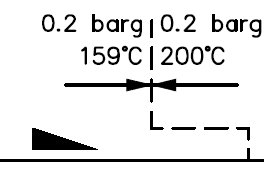
FYI1: the spec break is a break in specification. Most of the times we use them to identify a change in design pressure and/or design temperature, sometimes followed by change in pipe spec. We call out all (design) process data on PID. We usually have detailed operating info available too late. Also, design is usually some default margin (typically between 20-50 deg C) above the typical operating temperature the H&M balance data. So the extra margin is not that excessive
FYI2: when I talk design condition, Im referring to the p and T from PID spec break. See below for an example[/li]

[li]using the max p,T-range from pipe spec. I agree, that that is too conservative, but if you have no other data, then that's what you got to deal with.[/li]
[/ul]

specbreak_yqpn1i.png


Our line lists will have normal, max, and emergency conditions from our process group and our mechanical group then sets the design conditions.
I wish things would go that way, but we usually need to start piping design before such detailed info is available.

That's why we use the design conditions because they can't be (shouldn't be) worse than that. Every chemical plant I've worked at has a rotating door of process engineers and all the old heads who knew/designed the systems are gone.
Agreed. However, our default SS316 pipe spec goes to 400-425°C; when we use SS316 piping for e.g. a cooling water system (for our plants, linesizes are either tubing, or 1-3" piping, so CS is not commercially interesting, hence SS). We may have a design temperature on PID of say 120 °C (where max operating is around say 60°C). Now, it would be extremely and overly conservative to design such a system to 400°C, instead of 120°C, or even 60°C operating.

Huub
- You never get what you expect, you only get what you inspect.
 
I wish things would go that way, but we usually need to start piping design before such detailed info is available.

That's deeply unfortunate and quite frankly concerning. The process design should be pretty well established before piping design and pipe stress even get started. The P&ID's and line list are the upstream documents that we base our work on.

I'm curious what kinds of industries y'alls clients operate in.

Edward L. Klein
Pipe Stress Engineer
Houston, Texas

"All the world is a Spring"

All opinions expressed here are my own and not my company's.
 
We serve the typical chemical, oil and gas, pharmaceutical, bio-energy etc clients. And also the smaller startups that have a good idea. Typically for new technologies (pilots), where time to market (and funding quite often subsidy driven) is crucial.
Since technologies are new, a lot of things are different and hard to predict at forehand.
As such, design constraints are completely different to stick built project. Most of the stuff is modular.

Huub
- You never get what you expect, you only get what you inspect.
 
My stuff is general chemical industry, pulp & paper, and some power plant stuff, although naturally the power plant people are better.

Agreed with XL, my experience is similar. Clients just dont want to take the time to do things A -> B any more and/or the people who actually knew the process are gone. The newer process guys are just putting out fires and trying to tread above water before typically leaving.
 
Sometimes when anchor bolts are set or the pump and motor are installed "events" overcome the installation drawings and surprisingly large misalignments between the pimp flanges and piping will result.

If possible, an inspection "hold point" immediately before the piping is bolted to the pump can cause some problems at installation before commissioning.
Those problems generally are much easier ( NOT EASY) to deal with efficiently at the time than after the piping is pulled into "alignment" with come-alongs and the flange bolts are tightened and everybody goes home.

I'd say Designing the piping close to the pump with flexibility and adjustments is a real good idea.
As others said anchors close to the pump to handle the piping forces is a real good idea.

For fun, look at the stiffness of the flexible fittings you may be considering.
Sometimes the pump flanges need to be protected FROM them because the pump will not be protected BY them.
 
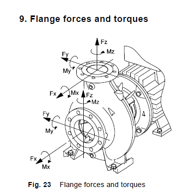
@LittleInch could you explain your modeling technique with anchoring/line stop close to the pump nozzle and flange as free ends? Using the nozzle limit check function it has to be applied to an anchor so how would I be able to check the flange? How can I review forces on that node with no restraint?
 
Status
Not open for further replies.

Part and Inventory Search

Sponsor